

120
3 Optical Signal Attenuation and Dispersion
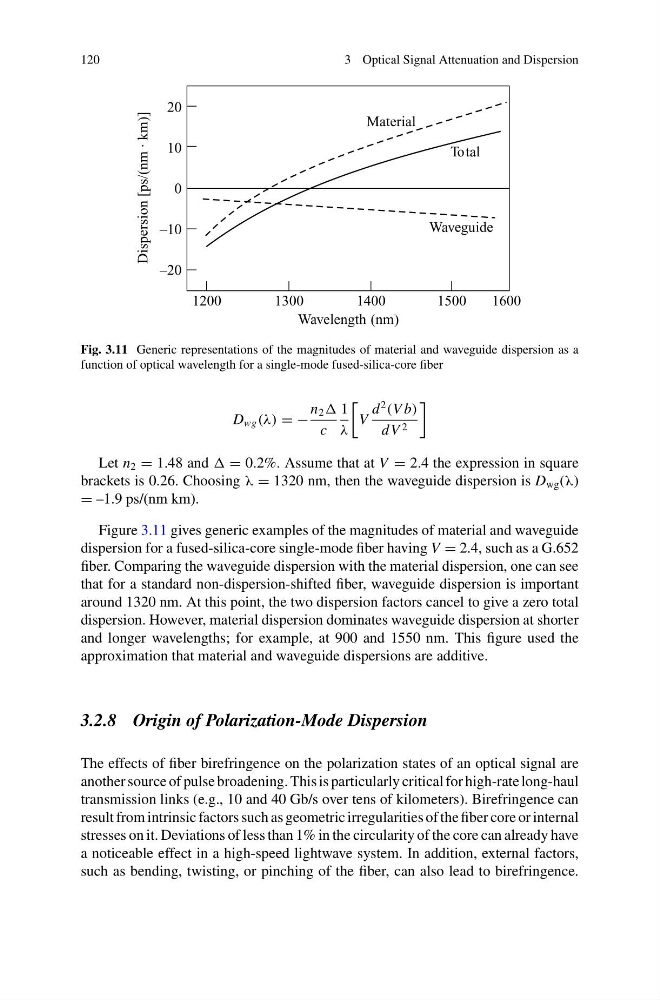
Fig. 3.11 Generic representations of the magnitudes of material and waveguide dispersion as a
function of optical wavelength for a single-mode fused-silica-core fiber
D wg (λ) = −
n 2
c
1
λ
V
d
2
(V b)
dV 2
Let n 2 = 1.48 and = 0.2%. Assume that at V = 2.4 the expression in square
brackets is 0.26. Choosing λ = 1320 nm, then the waveguide dispersion is D wg (λ)
= –1.9 ps/(nm km).
Figure 3.11 gives generic examples of the magnitudes of material and waveguide
dispersion for a fused-silica-core single-mode fiber having V = 2.4, such as a G.652
fiber. Comparing the waveguide dispersion with the material dispersion, one can see
that for a standard non-dispersion-shifted fiber, waveguide dispersion is important
around 1320 nm. At this point, the two dispersion factors cancel to give a zero total
dispersion. However, material dispersion dominates waveguide dispersion at shorter
and longer wavelengths; for example, at 900 and 1550 nm. This figure used the
approximation that material and waveguide dispersions are additive.
3.2.8 Origin of Polarization-Mode Dispersion
The effects of fiber birefringence on the polarization states of an optical signal are
another source of pulse broadening. This is particularly critical for high-rate long-haul
transmission links (e.g., 10 and 40 Gb/s over tens of kilometers). Birefringence can
result from intrinsic factors such as geometric irregularities of the fiber core or internal
stresses on it. Deviations of less than 1% in the circularity of the core can already have
a noticeable effect in a high-speed lightwave system. In addition, external factors,
such as bending, twisting, or pinching of the fiber, can also lead to birefringence.
3 Optical Signal Attenuation and Dispersion
Fig. 3.11 Generic representations of the magnitudes of material and waveguide dispersion as a
function of optical wavelength for a single-mode fused-silica-core fiber
D wg (λ) = −
n 2
c
1
λ
V
d
2
(V b)
dV 2
Let n 2 = 1.48 and = 0.2%. Assume that at V = 2.4 the expression in square
brackets is 0.26. Choosing λ = 1320 nm, then the waveguide dispersion is D wg (λ)
= –1.9 ps/(nm km).
Figure 3.11 gives generic examples of the magnitudes of material and waveguide
dispersion for a fused-silica-core single-mode fiber having V = 2.4, such as a G.652
fiber. Comparing the waveguide dispersion with the material dispersion, one can see
that for a standard non-dispersion-shifted fiber, waveguide dispersion is important
around 1320 nm. At this point, the two dispersion factors cancel to give a zero total
dispersion. However, material dispersion dominates waveguide dispersion at shorter
and longer wavelengths; for example, at 900 and 1550 nm. This figure used the
approximation that material and waveguide dispersions are additive.
3.2.8 Origin of Polarization-Mode Dispersion
The effects of fiber birefringence on the polarization states of an optical signal are
another source of pulse broadening. This is particularly critical for high-rate long-haul
transmission links (e.g., 10 and 40 Gb/s over tens of kilometers). Birefringence can
result from intrinsic factors such as geometric irregularities of the fiber core or internal
stresses on it. Deviations of less than 1% in the circularity of the core can already have
a noticeable effect in a high-speed lightwave system. In addition, external factors,
such as bending, twisting, or pinching of the fiber, can also lead to birefringence.