

3.1 Fiber Attenuation
105
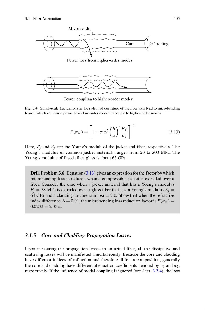
Fig. 3.4 Small-scale fluctuations in the radius of curvature of the fiber axis lead to microbending
losses, which can cause power from low-order modes to couple to higher-order modes
F(α M ) =
1 + ππ
2
b
a
4 E f
E j
−2
(3.13)
Here, E j and E f are the Young’s moduli of the jacket and fiber, respectively. The
Young’s modulus of common jacket materials ranges from 20 to 500 MPa. The
Young’s modulus of fused silica glass is about 65 GPa.
Drill Problem 3.6 Equation (3.13) gives an expression for the factor by which
microbending loss is reduced when a compressible jacket is extruded over a
fiber. Consider the case when a jacket material that has a Young’s modulus
E j = 58 MPa is extruded over a glass fiber that has a Young’s modulus E j =
64 GPa and a cladding-to-core ratio b/a = 2.0. Show that when the refractive
index difference = 0.01, the microbending loss reduction factor is F(α M ) =
0.0233 = 2.33%.
3.1.5 Core and Cladding Propagation Losses
Upon measuring the propagation losses in an actual fiber, all the dissipative and
scattering losses will be manifested simultaneously. Because the core and cladding
have different indices of refraction and therefore differ in composition, generally
the core and cladding have different attenuation coefficients denoted by α 1 and α 2 ,
respectively. If the influence of modal coupling is ignored (see Sect. 3.2.4), the loss
105
Fig. 3.4 Small-scale fluctuations in the radius of curvature of the fiber axis lead to microbending
losses, which can cause power from low-order modes to couple to higher-order modes
F(α M ) =
1 + ππ
2
b
a
4 E f
E j
−2
(3.13)
Here, E j and E f are the Young’s moduli of the jacket and fiber, respectively. The
Young’s modulus of common jacket materials ranges from 20 to 500 MPa. The
Young’s modulus of fused silica glass is about 65 GPa.
Drill Problem 3.6 Equation (3.13) gives an expression for the factor by which
microbending loss is reduced when a compressible jacket is extruded over a
fiber. Consider the case when a jacket material that has a Young’s modulus
E j = 58 MPa is extruded over a glass fiber that has a Young’s modulus E j =
64 GPa and a cladding-to-core ratio b/a = 2.0. Show that when the refractive
index difference = 0.01, the microbending loss reduction factor is F(α M ) =
0.0233 = 2.33%.
3.1.5 Core and Cladding Propagation Losses
Upon measuring the propagation losses in an actual fiber, all the dissipative and
scattering losses will be manifested simultaneously. Because the core and cladding
have different indices of refraction and therefore differ in composition, generally
the core and cladding have different attenuation coefficients denoted by α 1 and α 2 ,
respectively. If the influence of modal coupling is ignored (see Sect. 3.2.4), the loss