

Chapter 8 for methods such as SPR or DPI; however, for the EO effect, the
change in index comes from the applied field instead of from the addition
or removal of an adsorbate.
The electro-optic coefficient is in turn proportional to the second-order
susceptibility (c 2 ), which, for a molecular material, is proportional to the
concentration (N), hyperpolarizability (b), and degree of acentric order
〈cos
3 q〉 of the material:
r 33 =
−2c 2 w, 0
ð
Þ
n
4 w
ð Þ
∝ Nb cos
3 q
(10.8)
Thus, a well-ordered material with a large hyperpolarizability yields a large
electro-optic coefficient, which allows obtaining the same refractive index
shift using a weaker electric field than in a lower-performing material.
10.8.2 Organic–inorganic hybrid electro-optics
Present electro-optic systems are typically based on crystalline inorganic
materials such as LiNbO 3 (r 33 = 31 pm/V), which is adequate for macroscopic devices. However, ferroelectric crystals such as LiNbO 3 are not
readily integrated into nanoscale integrated circuits due to their structure
and the requirement of using high voltages to obtain a sufficient refractive
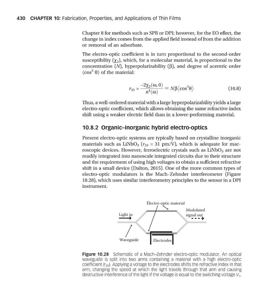
shift in a small device (Dalton, 2015). One of the more common types of
electro-optic modulators is the Mach–Zehnder interferometer (Figure
10.28), which uses similar interferometry principles to the sensor in a DPI
instrument.
Light in
Modulated
signal out
Electrodes
Electro-optic material
Waveguide
Figure 10.28 Schematic of a Mach–Zehnder electro-optic modulator. An optical
waveguide is split into two arms containing a material with a high electro-optic
coefficient (r 33 ). Applying a voltage to the electrodes shifts the refractive index in that
arm, changing the speed at which the light travels through that arm and causing
destructive interference of the light if the voltage is equal to the switching voltage V π .
CHAPTER 10: Fabrication, Properties, and Applications of Thin Films
430
change in index comes from the applied field instead of from the addition
or removal of an adsorbate.
The electro-optic coefficient is in turn proportional to the second-order
susceptibility (c 2 ), which, for a molecular material, is proportional to the
concentration (N), hyperpolarizability (b), and degree of acentric order
〈cos
3 q〉 of the material:
r 33 =
−2c 2 w, 0
ð
Þ
n
4 w
ð Þ
∝ Nb cos
3 q
(10.8)
Thus, a well-ordered material with a large hyperpolarizability yields a large
electro-optic coefficient, which allows obtaining the same refractive index
shift using a weaker electric field than in a lower-performing material.
10.8.2 Organic–inorganic hybrid electro-optics
Present electro-optic systems are typically based on crystalline inorganic
materials such as LiNbO 3 (r 33 = 31 pm/V), which is adequate for macroscopic devices. However, ferroelectric crystals such as LiNbO 3 are not
readily integrated into nanoscale integrated circuits due to their structure
and the requirement of using high voltages to obtain a sufficient refractive
shift in a small device (Dalton, 2015). One of the more common types of
electro-optic modulators is the Mach–Zehnder interferometer (Figure
10.28), which uses similar interferometry principles to the sensor in a DPI
instrument.
Light in
Modulated
signal out
Electrodes
Electro-optic material
Waveguide
Figure 10.28 Schematic of a Mach–Zehnder electro-optic modulator. An optical
waveguide is split into two arms containing a material with a high electro-optic
coefficient (r 33 ). Applying a voltage to the electrodes shifts the refractive index in that
arm, changing the speed at which the light travels through that arm and causing
destructive interference of the light if the voltage is equal to the switching voltage V π .
CHAPTER 10: Fabrication, Properties, and Applications of Thin Films
430