

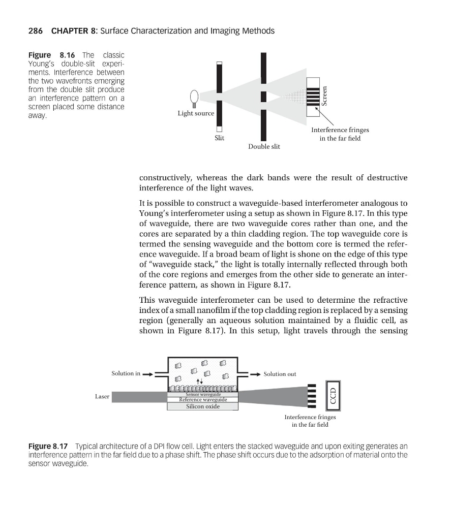
constructively, whereas the dark bands were the result of destructive
interference of the light waves.
It is possible to construct a waveguide-based interferometer analogous to
Young’s interferometer using a setup as shown in Figure 8.17. In this type
of waveguide, there are two waveguide cores rather than one, and the
cores are separated by a thin cladding region. The top waveguide core is
termed the sensing waveguide and the bottom core is termed the reference waveguide. If a broad beam of light is shone on the edge of this type
of “waveguide stack,” the light is totally internally reflected through both
of the core regions and emerges from the other side to generate an interference pattern, as shown in Figure 8.17.
This waveguide interferometer can be used to determine the refractive
index of a small nanofilm if the top cladding region is replaced by a sensing
region (generally an aqueous solution maintained by a fluidic cell, as
shown in Figure 8.17). In this setup, light travels through the sensing
Sensor waveguide
Solution in
Solution out
CCD
Silicon oxide
Interference fringes
in the far field
Laser
Reference waveguide
Figure 8.17 Typical architecture of a DPI flow cell. Light enters the stacked waveguide and upon exiting generates an
interference pattern in the far field due to a phase shift. The phase shift occurs due to the adsorption of material onto the
sensor waveguide.
Screen
Light source
Slit
Double slit
Interference fringes
in the far field
Figure 8.16 The classic
Young’s double-slit experiments. Interference between
the two wavefronts emerging
from the double slit produce
an interference pattern on a
screen placed some distance
away.
CHAPTER 8: Surface Characterization and Imaging Methods
286
interference of the light waves.
It is possible to construct a waveguide-based interferometer analogous to
Young’s interferometer using a setup as shown in Figure 8.17. In this type
of waveguide, there are two waveguide cores rather than one, and the
cores are separated by a thin cladding region. The top waveguide core is
termed the sensing waveguide and the bottom core is termed the reference waveguide. If a broad beam of light is shone on the edge of this type
of “waveguide stack,” the light is totally internally reflected through both
of the core regions and emerges from the other side to generate an interference pattern, as shown in Figure 8.17.
This waveguide interferometer can be used to determine the refractive
index of a small nanofilm if the top cladding region is replaced by a sensing
region (generally an aqueous solution maintained by a fluidic cell, as
shown in Figure 8.17). In this setup, light travels through the sensing
Sensor waveguide
Solution in
Solution out
CCD
Silicon oxide
Interference fringes
in the far field
Laser
Reference waveguide
Figure 8.17 Typical architecture of a DPI flow cell. Light enters the stacked waveguide and upon exiting generates an
interference pattern in the far field due to a phase shift. The phase shift occurs due to the adsorption of material onto the
sensor waveguide.
Screen
Light source
Slit
Double slit
Interference fringes
in the far field
Figure 8.16 The classic
Young’s double-slit experiments. Interference between
the two wavefronts emerging
from the double slit produce
an interference pattern on a
screen placed some distance
away.
CHAPTER 8: Surface Characterization and Imaging Methods
286