

8.3.4 The ellipsometer
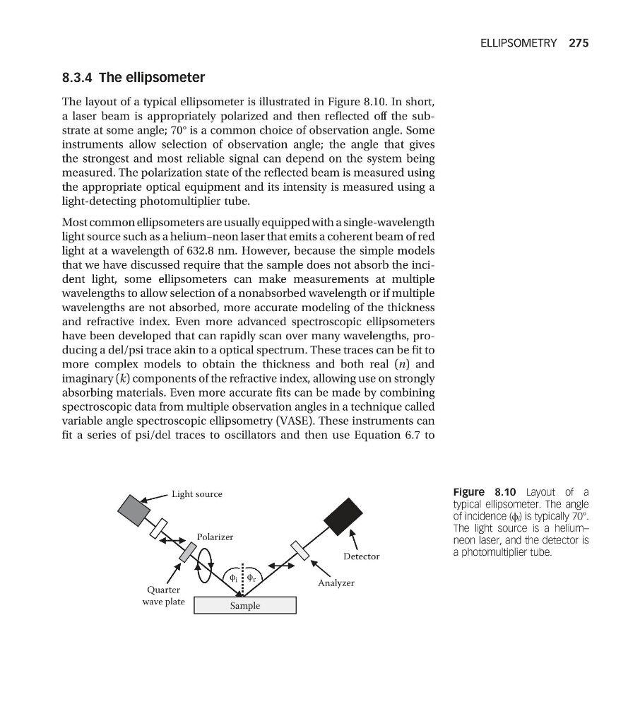
The layout of a typical ellipsometer is illustrated in Figure 8.10. In short,
a laser beam is appropriately polarized and then reflected off the substrate at some angle; 70° is a common choice of observation angle. Some
instruments allow selection of observation angle; the angle that gives
the strongest and most reliable signal can depend on the system being
measured. The polarization state of the reflected beam is measured using
the appropriate optical equipment and its intensity is measured using a
light-detecting photomultiplier tube.
Most common ellipsometers are usually equipped with a single-wavelength
light source such as a helium–neon laser that emits a coherent beam of red
light at a wavelength of 632.8 nm. However, because the simple models
that we have discussed require that the sample does not absorb the incident light, some ellipsometers can make measurements at multiple
wavelengths to allow selection of a nonabsorbed wavelength or if multiple
wavelengths are not absorbed, more accurate modeling of the thickness
and refractive index. Even more advanced spectroscopic ellipsometers
have been developed that can rapidly scan over many wavelengths, producing a del/psi trace akin to a optical spectrum. These traces can be fit to
more complex models to obtain the thickness and both real (n) and
imaginary (k) components of the refractive index, allowing use on strongly
absorbing materials. Even more accurate fits can be made by combining
spectroscopic data from multiple observation angles in a technique called
variable angle spectroscopic ellipsometry (VASE). These instruments can
fit a series of psi/del traces to oscillators and then use Equation 6.7 to
Light source
Polarizer
φ r
φ i
Detector
Quarter
wave plate
Analyzer
Sample
Figure 8.10 Layout of a
typical ellipsometer. The angle
of incidence (ϕ i ) is typically 70°.
The light source is a helium–
neon laser, and the detector is
a photomultiplier tube.
ELLIPSOMETRY 275
The layout of a typical ellipsometer is illustrated in Figure 8.10. In short,
a laser beam is appropriately polarized and then reflected off the substrate at some angle; 70° is a common choice of observation angle. Some
instruments allow selection of observation angle; the angle that gives
the strongest and most reliable signal can depend on the system being
measured. The polarization state of the reflected beam is measured using
the appropriate optical equipment and its intensity is measured using a
light-detecting photomultiplier tube.
Most common ellipsometers are usually equipped with a single-wavelength
light source such as a helium–neon laser that emits a coherent beam of red
light at a wavelength of 632.8 nm. However, because the simple models
that we have discussed require that the sample does not absorb the incident light, some ellipsometers can make measurements at multiple
wavelengths to allow selection of a nonabsorbed wavelength or if multiple
wavelengths are not absorbed, more accurate modeling of the thickness
and refractive index. Even more advanced spectroscopic ellipsometers
have been developed that can rapidly scan over many wavelengths, producing a del/psi trace akin to a optical spectrum. These traces can be fit to
more complex models to obtain the thickness and both real (n) and
imaginary (k) components of the refractive index, allowing use on strongly
absorbing materials. Even more accurate fits can be made by combining
spectroscopic data from multiple observation angles in a technique called
variable angle spectroscopic ellipsometry (VASE). These instruments can
fit a series of psi/del traces to oscillators and then use Equation 6.7 to
Light source
Polarizer
φ r
φ i
Detector
Quarter
wave plate
Analyzer
Sample
Figure 8.10 Layout of a
typical ellipsometer. The angle
of incidence (ϕ i ) is typically 70°.
The light source is a helium–
neon laser, and the detector is
a photomultiplier tube.
ELLIPSOMETRY 275