

5.2 Critical State Model
81
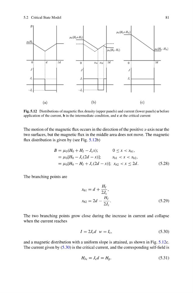
Fig. 5.12 Distributions of magnetic flux density (upper panels) and current (lower panels) a before
application of the current, b in the intermediate condition, and c at the critical current
The motion of the magnetic flux occurs in the direction of the positive x-axis near the
two surfaces, but the magnetic flux in the middle area does not move. The magnetic
flux distribution is given by (see Fig. 5.12b)
B = μ 0 (H 0 + H I − J c x);
0 ≤ x < x b1 ,
= μ 0 [H 0 − J c (2d − x)];
x b1 < x < x b2 ,
= μ 0 [H 0 − H I + J c (2d − x)]; x b2 < x ≤ 2d .
(5.28)
The branching points are
x b1 = d +
H I
2J c
,
x b2 = 2d −
H I
2J c
.
(5.29)
The two branching points grow close during the increase in current and collapse
when the current reaches
I = 2J c d w = I c ,
(5.30)
and a magnetic distribution with a uniform slope is attained, as shown in Fig. 5.12c.
The current given by (5.30) is the critical current, and the corresponding self-field is
H I c = J c d = H p .
(5.31)
81
Fig. 5.12 Distributions of magnetic flux density (upper panels) and current (lower panels) a before
application of the current, b in the intermediate condition, and c at the critical current
The motion of the magnetic flux occurs in the direction of the positive x-axis near the
two surfaces, but the magnetic flux in the middle area does not move. The magnetic
flux distribution is given by (see Fig. 5.12b)
B = μ 0 (H 0 + H I − J c x);
0 ≤ x < x b1 ,
= μ 0 [H 0 − J c (2d − x)];
x b1 < x < x b2 ,
= μ 0 [H 0 − H I + J c (2d − x)]; x b2 < x ≤ 2d .
(5.28)
The branching points are
x b1 = d +
H I
2J c
,
x b2 = 2d −
H I
2J c
.
(5.29)
The two branching points grow close during the increase in current and collapse
when the current reaches
I = 2J c d w = I c ,
(5.30)
and a magnetic distribution with a uniform slope is attained, as shown in Fig. 5.12c.
The current given by (5.30) is the critical current, and the corresponding self-field is
H I c = J c d = H p .
(5.31)