

184
Appendix
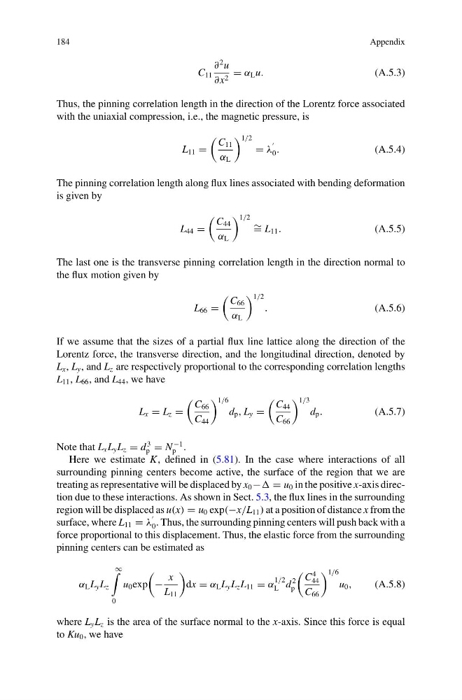
C 11
∂
2 u
∂x 2 = α L u.
(A.5.3)
Thus, the pinning correlation length in the direction of the Lorentz force associated
with the uniaxial compression, i.e., the magnetic pressure, is
L 11 =
C 11
α L
1/2
= λ
0 .
(A.5.4)
The pinning correlation length along flux lines associated with bending deformation
is given by
L 44 =
C 44
α L
1/2 ∼ = L 11 .
(A.5.5)
The last one is the transverse pinning correlation length in the direction normal to
the flux motion given by
L 66 =
C 66
α L
1/2
.
(A.5.6)
If we assume that the sizes of a partial flux line lattice along the direction of the
Lorentz force, the transverse direction, and the longitudinal direction, denoted by
L x , L y , and L z are respectively proportional to the corresponding correlation lengths
L 11 , L 66 , and L 44 , we have
L x = L z =
C 66
C 44
1/6
d p , L y =
C 44
C 66
1/3
d p .
(A.5.7)
Note that L x L y L z = d
3
p = N
−1
p .
Here we estimate K, defined in (5.81). In the case where interactions of all
surrounding pinning centers become active, the surface of the region that we are
treating as representative will be displaced by x 0 − = u 0 in the positive x-axis direction due to these interactions. As shown in Sect. 5.3, the flux lines in the surrounding
region will be displaced as u(x) = u 0 exp(−x/L 11 ) at a position of distance x from the
surface, where L 11 = λ
0 . Thus, the surrounding pinning centers will push back with a
force proportional to this displacement. Thus, the elastic force from the surrounding
pinning centers can be estimated as
α L L y L z
∞
0
u 0 exp
−
x
L 11
dx = α L L y L z L 11 = α
1/2
L d
2
p
C
4
44
C 66
1/6
u 0 ,
(A.5.8)
where L y L z is the area of the surface normal to the x-axis. Since this force is equal
to Ku 0 , we have
Appendix
C 11
∂
2 u
∂x 2 = α L u.
(A.5.3)
Thus, the pinning correlation length in the direction of the Lorentz force associated
with the uniaxial compression, i.e., the magnetic pressure, is
L 11 =
C 11
α L
1/2
= λ
0 .
(A.5.4)
The pinning correlation length along flux lines associated with bending deformation
is given by
L 44 =
C 44
α L
1/2 ∼ = L 11 .
(A.5.5)
The last one is the transverse pinning correlation length in the direction normal to
the flux motion given by
L 66 =
C 66
α L
1/2
.
(A.5.6)
If we assume that the sizes of a partial flux line lattice along the direction of the
Lorentz force, the transverse direction, and the longitudinal direction, denoted by
L x , L y , and L z are respectively proportional to the corresponding correlation lengths
L 11 , L 66 , and L 44 , we have
L x = L z =
C 66
C 44
1/6
d p , L y =
C 44
C 66
1/3
d p .
(A.5.7)
Note that L x L y L z = d
3
p = N
−1
p .
Here we estimate K, defined in (5.81). In the case where interactions of all
surrounding pinning centers become active, the surface of the region that we are
treating as representative will be displaced by x 0 − = u 0 in the positive x-axis direction due to these interactions. As shown in Sect. 5.3, the flux lines in the surrounding
region will be displaced as u(x) = u 0 exp(−x/L 11 ) at a position of distance x from the
surface, where L 11 = λ
0 . Thus, the surrounding pinning centers will push back with a
force proportional to this displacement. Thus, the elastic force from the surrounding
pinning centers can be estimated as
α L L y L z
∞
0
u 0 exp
−
x
L 11
dx = α L L y L z L 11 = α
1/2
L d
2
p
C
4
44
C 66
1/6
u 0 ,
(A.5.8)
where L y L z is the area of the surface normal to the x-axis. Since this force is equal
to Ku 0 , we have