

Appendix
183
The second integral in the braces is calculated as
a f
f p − f pt
3
2η ∗ f
2
pt
.
(A.4.7)
Thus, the pinning loss power density is given by
P p =
N p η
∗ v
a f
·
a f
2η ∗
f p − f pt
2
f p + f pt
+ f p − f pt
=
N p f p
f p − f pt
v
f p + f pt
.
(A.4.8)
A.5 Derivation of (5.86)
Here, we discuss the structure of a partial flux line lattice that is treated representatively in the statistical treatment. For this purpose, the pinning correlation lengths
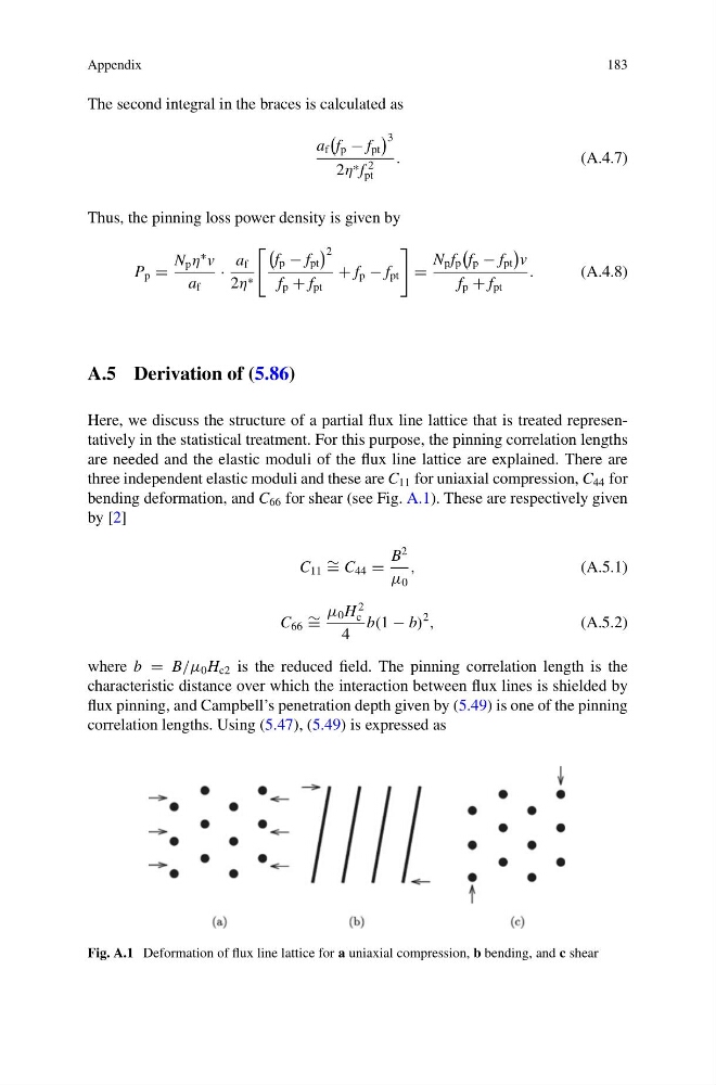
are needed and the elastic moduli of the flux line lattice are explained. There are
three independent elastic moduli and these are C 11 for uniaxial compression, C 44 for
bending deformation, and C 66 for shear (see Fig. A.1). These are respectively given
by [2]
C 11 ∼ = C 44 =
B
2
μ 0
,
(A.5.1)
C 66 ∼ =
μ 0 H
2
c
4
b(1 − b)
2
,
(A.5.2)
where b = B/μ 0 H c2 is the reduced field. The pinning correlation length is the
characteristic distance over which the interaction between flux lines is shielded by
flux pinning, and Campbell’s penetration depth given by (5.49) is one of the pinning
correlation lengths. Using (5.47), (5.49) is expressed as
Fig. A.1 Deformation of flux line lattice for a uniaxial compression, b bending, and c shear
183
The second integral in the braces is calculated as
a f
f p − f pt
3
2η ∗ f
2
pt
.
(A.4.7)
Thus, the pinning loss power density is given by
P p =
N p η
∗ v
a f
·
a f
2η ∗
f p − f pt
2
f p + f pt
+ f p − f pt
=
N p f p
f p − f pt
v
f p + f pt
.
(A.4.8)
A.5 Derivation of (5.86)
Here, we discuss the structure of a partial flux line lattice that is treated representatively in the statistical treatment. For this purpose, the pinning correlation lengths
are needed and the elastic moduli of the flux line lattice are explained. There are
three independent elastic moduli and these are C 11 for uniaxial compression, C 44 for
bending deformation, and C 66 for shear (see Fig. A.1). These are respectively given
by [2]
C 11 ∼ = C 44 =
B
2
μ 0
,
(A.5.1)
C 66 ∼ =
μ 0 H
2
c
4
b(1 − b)
2
,
(A.5.2)
where b = B/μ 0 H c2 is the reduced field. The pinning correlation length is the
characteristic distance over which the interaction between flux lines is shielded by
flux pinning, and Campbell’s penetration depth given by (5.49) is one of the pinning
correlation lengths. Using (5.47), (5.49) is expressed as
Fig. A.1 Deformation of flux line lattice for a uniaxial compression, b bending, and c shear