

148
6 Longitudinal Magnetic Field Effect
Table 6.2 General comparison of electromagnetic phenomena between the transverse and
longitudinal magnetic fields
Transverse magnetic field
Longitudinal magnetic
field
Distortion of flux lines
Magnetic pressure strain
(gradient of density) and tilt
distortion
Rotational shearing
distortion
Balance equation
F L + F p = 0
+ p = 0
Principle of minimum energy
dissipation
Holds
Holds
Flux motion for I < I c and I > I c Translational motion
Rotational motion +
translational motion
Induced electric field
E = B × v
E = B × v − ∇φ
Magnetic helicity
A · B = 0
A · B = 0
natural, however, since the electromagnetic phenomena arising from the longitudinal
magnetic field effects exceed the traditional framework of electromagnetism.
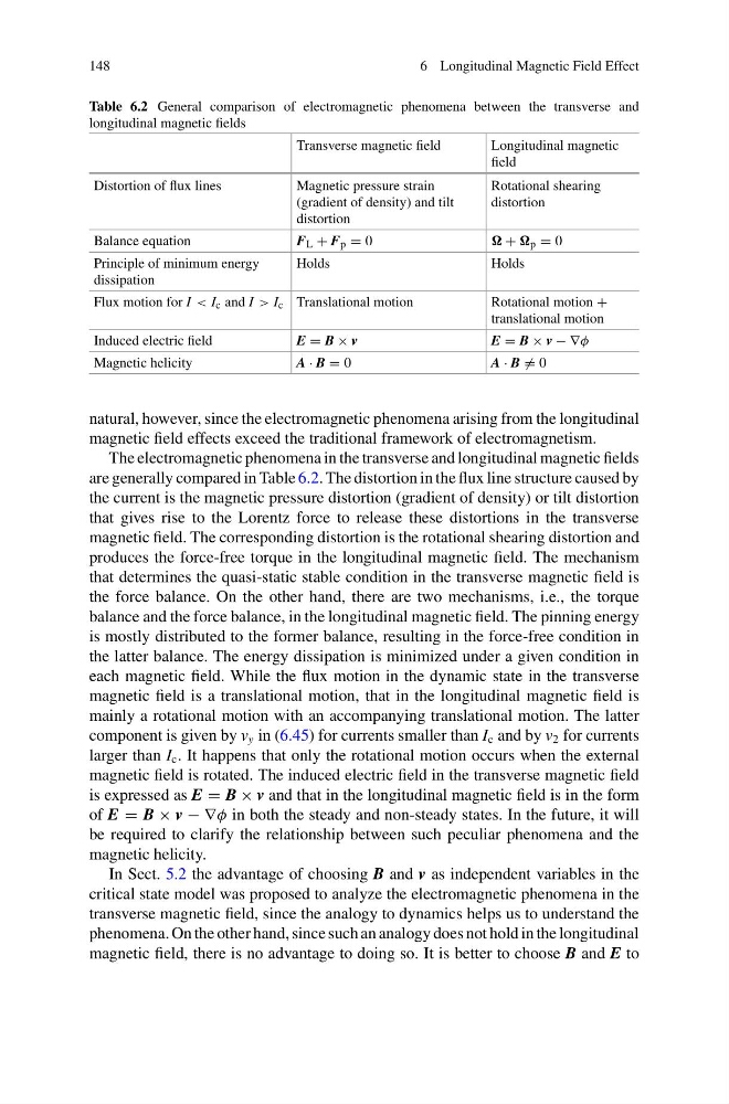
The electromagnetic phenomena in the transverse and longitudinal magnetic fields
are generally compared in Table 6.2. The distortion in the flux line structure caused by
the current is the magnetic pressure distortion (gradient of density) or tilt distortion
that gives rise to the Lorentz force to release these distortions in the transverse
magnetic field. The corresponding distortion is the rotational shearing distortion and
produces the force-free torque in the longitudinal magnetic field. The mechanism
that determines the quasi-static stable condition in the transverse magnetic field is
the force balance. On the other hand, there are two mechanisms, i.e., the torque
balance and the force balance, in the longitudinal magnetic field. The pinning energy
is mostly distributed to the former balance, resulting in the force-free condition in
the latter balance. The energy dissipation is minimized under a given condition in
each magnetic field. While the flux motion in the dynamic state in the transverse
magnetic field is a translational motion, that in the longitudinal magnetic field is
mainly a rotational motion with an accompanying translational motion. The latter
component is given by v y in (6.45) for currents smaller than I c and by v 2 for currents
larger than I c . It happens that only the rotational motion occurs when the external
magnetic field is rotated. The induced electric field in the transverse magnetic field
is expressed as E = B × v and that in the longitudinal magnetic field is in the form
of E = B × v − ∇φ in both the steady and non-steady states. In the future, it will
be required to clarify the relationship between such peculiar phenomena and the
magnetic helicity.
In Sect. 5.2 the advantage of choosing B and v as independent variables in the
critical state model was proposed to analyze the electromagnetic phenomena in the
transverse magnetic field, since the analogy to dynamics helps us to understand the
phenomena. On the other hand, since such an analogy does not hold in the longitudinal
magnetic field, there is no advantage to doing so. It is better to choose B and E to
6 Longitudinal Magnetic Field Effect
Table 6.2 General comparison of electromagnetic phenomena between the transverse and
longitudinal magnetic fields
Transverse magnetic field
Longitudinal magnetic
field
Distortion of flux lines
Magnetic pressure strain
(gradient of density) and tilt
distortion
Rotational shearing
distortion
Balance equation
F L + F p = 0
+ p = 0
Principle of minimum energy
dissipation
Holds
Holds
Flux motion for I < I c and I > I c Translational motion
Rotational motion +
translational motion
Induced electric field
E = B × v
E = B × v − ∇φ
Magnetic helicity
A · B = 0
A · B = 0
natural, however, since the electromagnetic phenomena arising from the longitudinal
magnetic field effects exceed the traditional framework of electromagnetism.
The electromagnetic phenomena in the transverse and longitudinal magnetic fields
are generally compared in Table 6.2. The distortion in the flux line structure caused by
the current is the magnetic pressure distortion (gradient of density) or tilt distortion
that gives rise to the Lorentz force to release these distortions in the transverse
magnetic field. The corresponding distortion is the rotational shearing distortion and
produces the force-free torque in the longitudinal magnetic field. The mechanism
that determines the quasi-static stable condition in the transverse magnetic field is
the force balance. On the other hand, there are two mechanisms, i.e., the torque
balance and the force balance, in the longitudinal magnetic field. The pinning energy
is mostly distributed to the former balance, resulting in the force-free condition in
the latter balance. The energy dissipation is minimized under a given condition in
each magnetic field. While the flux motion in the dynamic state in the transverse
magnetic field is a translational motion, that in the longitudinal magnetic field is
mainly a rotational motion with an accompanying translational motion. The latter
component is given by v y in (6.45) for currents smaller than I c and by v 2 for currents
larger than I c . It happens that only the rotational motion occurs when the external
magnetic field is rotated. The induced electric field in the transverse magnetic field
is expressed as E = B × v and that in the longitudinal magnetic field is in the form
of E = B × v − ∇φ in both the steady and non-steady states. In the future, it will
be required to clarify the relationship between such peculiar phenomena and the
magnetic helicity.
In Sect. 5.2 the advantage of choosing B and v as independent variables in the
critical state model was proposed to analyze the electromagnetic phenomena in the
transverse magnetic field, since the analogy to dynamics helps us to understand the
phenomena. On the other hand, since such an analogy does not hold in the longitudinal
magnetic field, there is no advantage to doing so. It is better to choose B and E to