

130
6 Longitudinal Magnetic Field Effect
structure shown in Fig. 6.11, which is different from the common process of applying
a magnetic field and then applying a transport current. This can be achieved by
rotating the applied magnetic field. In the usual process the penetration of magnetic
flux driven by the Lorentz force also occurs due to the self-field, resulting in a complex
situation. Some experiments corresponding to the assumed process have been done.
In this case, a uniform rotation of the magnetic flux is not easy, and hence, the superconductor is rotated in a uniform magnetic field, since the condition is relativistically
the same.
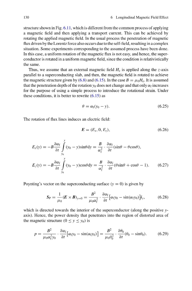
Thus, we assume that an external magnetic field H e is applied along the z-axis
parallel to a superconducting slab, and then, the magnetic field is rotated to achieve
the magnetic structure given by (6.8) and (6.15). In the case B = μ 0 H e . It is assumed
that the penetration depth of the rotation y 0 does not change and that only α f increases
for the purpose of using a simple process to introduce the rotational strain. Under
these conditions, it is better to rewrite (6.15) as
θ = α f (y 0 − y).
(6.25)
The rotation of flux lines induces an electric field:
E = (E x , 0, E z ),
(6.26)
E x (y) = −B
∂α f
∂t
y
y 0
(y 0 − y)sinθ dy =
B
α
2
f
·
∂α f
∂t
(sinθ − θ cosθ ),
E z (y) = −B
∂α f
∂t
y
y 0
(y 0 − y)cosθ dy =
B
α
2
f
·
∂α f
∂t
(θ sinθ + cosθ − 1).
(6.27)
Poynting’s vector on the superconducting surface (y = 0) is given by
S P =
1
μ 0
(E × B) y=0 =
B
2
μ 0 α
2
f
·
∂α f
∂t
α f y 0 − sin(α f y 0 )
i y ,
(6.28)
which is directed towards the interior of the superconductor (along the positive yaxis). Hence, the power density that penetrates into the region of distorted area of
the magnetic structure (0 ≤ y ≤ y 0 ) is
p =
B
2
μ 0 α
2
f y 0
·
∂α f
∂t
α f y 0 − sin(α f y 0 )
=
B
2
μ 0 θ
2
0
·
∂θ 0
∂t
(θ 0 − sinθ 0 ).
(6.29)
6 Longitudinal Magnetic Field Effect
structure shown in Fig. 6.11, which is different from the common process of applying
a magnetic field and then applying a transport current. This can be achieved by
rotating the applied magnetic field. In the usual process the penetration of magnetic
flux driven by the Lorentz force also occurs due to the self-field, resulting in a complex
situation. Some experiments corresponding to the assumed process have been done.
In this case, a uniform rotation of the magnetic flux is not easy, and hence, the superconductor is rotated in a uniform magnetic field, since the condition is relativistically
the same.
Thus, we assume that an external magnetic field H e is applied along the z-axis
parallel to a superconducting slab, and then, the magnetic field is rotated to achieve
the magnetic structure given by (6.8) and (6.15). In the case B = μ 0 H e . It is assumed
that the penetration depth of the rotation y 0 does not change and that only α f increases
for the purpose of using a simple process to introduce the rotational strain. Under
these conditions, it is better to rewrite (6.15) as
θ = α f (y 0 − y).
(6.25)
The rotation of flux lines induces an electric field:
E = (E x , 0, E z ),
(6.26)
E x (y) = −B
∂α f
∂t
y
y 0
(y 0 − y)sinθ dy =
B
α
2
f
·
∂α f
∂t
(sinθ − θ cosθ ),
E z (y) = −B
∂α f
∂t
y
y 0
(y 0 − y)cosθ dy =
B
α
2
f
·
∂α f
∂t
(θ sinθ + cosθ − 1).
(6.27)
Poynting’s vector on the superconducting surface (y = 0) is given by
S P =
1
μ 0
(E × B) y=0 =
B
2
μ 0 α
2
f
·
∂α f
∂t
α f y 0 − sin(α f y 0 )
i y ,
(6.28)
which is directed towards the interior of the superconductor (along the positive yaxis). Hence, the power density that penetrates into the region of distorted area of
the magnetic structure (0 ≤ y ≤ y 0 ) is
p =
B
2
μ 0 α
2
f y 0
·
∂α f
∂t
α f y 0 − sin(α f y 0 )
=
B
2
μ 0 θ
2
0
·
∂θ 0
∂t
(θ 0 − sinθ 0 ).
(6.29)