

6.2 Clue to the Solution
125
B = Bi B ,
(6.3)
where i B is a unit vector directed along B. Then, the current density is
J =
1
μ 0
∇ × B = −
1
μ 0
(i B × ∇)B +
1
μ 0
B∇ × i B .
(6.4)
Since the first term is normal to B, it is not a force-free component. The second term
is important. It is assumed for simplicity that the vector B stays in the x-z plane. Its
angle from the z-axis is denoted by θ . Using the unit vectors i x and i z along the xand z-axis, i B is written as
i B = i x sinθ + i z cosθ.
(6.5)
If we assume that the angle θ varies only along the y-axis, the second term in (6.4)
is reduced to
J =
1
μ 0
·
∂B
∂y
i L −
B
μ 0
·
∂θ
∂y
i B ,
(6.6)
where
i L = i x cosθ − i z sinθ.
(6.7)
The first term in (6.6) is the current caused by the Lorentz force, i.e., the magnetic
pressure, as expected. The second current is parallel to the magnetic flux density,
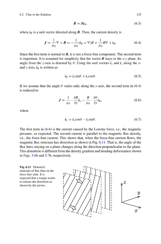
i.e., the force-free current. This shows that, when the force-free current flows, the
magnetic flux structure has distortion as shown in Fig. 6.11. That is, the angle of the
flux lines staying on a plane changes along the direction perpendicular to the plane.
This distortion is different from the density gradient and bending deformation shown
in Figs. 5.6b and 5.7b, respectively.
Fig. 6.11 Distorted
structure of flux lines in the
force-free state. It is
expected that a torque works
to release the distortion as
shown by the arrows
125
B = Bi B ,
(6.3)
where i B is a unit vector directed along B. Then, the current density is
J =
1
μ 0
∇ × B = −
1
μ 0
(i B × ∇)B +
1
μ 0
B∇ × i B .
(6.4)
Since the first term is normal to B, it is not a force-free component. The second term
is important. It is assumed for simplicity that the vector B stays in the x-z plane. Its
angle from the z-axis is denoted by θ . Using the unit vectors i x and i z along the xand z-axis, i B is written as
i B = i x sinθ + i z cosθ.
(6.5)
If we assume that the angle θ varies only along the y-axis, the second term in (6.4)
is reduced to
J =
1
μ 0
·
∂B
∂y
i L −
B
μ 0
·
∂θ
∂y
i B ,
(6.6)
where
i L = i x cosθ − i z sinθ.
(6.7)
The first term in (6.6) is the current caused by the Lorentz force, i.e., the magnetic
pressure, as expected. The second current is parallel to the magnetic flux density,
i.e., the force-free current. This shows that, when the force-free current flows, the
magnetic flux structure has distortion as shown in Fig. 6.11. That is, the angle of the
flux lines staying on a plane changes along the direction perpendicular to the plane.
This distortion is different from the density gradient and bending deformation shown
in Figs. 5.6b and 5.7b, respectively.
Fig. 6.11 Distorted
structure of flux lines in the
force-free state. It is
expected that a torque works
to release the distortion as
shown by the arrows