

4.7 Synthesis of Coated Particles 73
surface. As the movement of the electrons is random in all directions, it is
quite difficult to estimate the maximum allowed distance between the two
reaction zones.
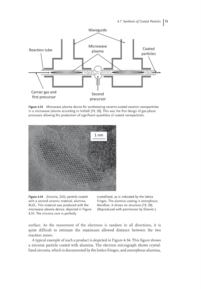
A typical example of such a product is depicted in Figure 4.34. This figure shows
a zirconia particle coated with alumina. The electron micrograph shows crystallized zirconia, which is documented by the lattice fringes, and amorphous alumina,
Figure 4.33 Microwave plasma device for synthesizing ceramic-coated ceramic nanoparticles
in a microwave plasma according to Vollath [19, 20]. This was the first design of gas-phase
processes allowing the production of significant quantities of coated nanoparticles.
Waveguide
Coated
parƟcles
Microwave
plasma
ReacƟon tube
Carrier gas and
first precursor
Second
precursor
Figure 4.34 Zirconia, ZrO 2 particle coated
with a second ceramic material, alumina,
Al 2 O 3 . This material was produced with the
microwave plasma device, depicted in Figure
4.33. The zirconia core is perfectly
crystallized, as is indicated by the lattice
fringes. The alumina coating is amorphous;
therefore, it shows no structure [19, 20].
(Reproduced with permission by Elsevier.)
1 nm
surface. As the movement of the electrons is random in all directions, it is
quite difficult to estimate the maximum allowed distance between the two
reaction zones.
A typical example of such a product is depicted in Figure 4.34. This figure shows
a zirconia particle coated with alumina. The electron micrograph shows crystallized zirconia, which is documented by the lattice fringes, and amorphous alumina,
Figure 4.33 Microwave plasma device for synthesizing ceramic-coated ceramic nanoparticles
in a microwave plasma according to Vollath [19, 20]. This was the first design of gas-phase
processes allowing the production of significant quantities of coated nanoparticles.
Waveguide
Coated
parƟcles
Microwave
plasma
ReacƟon tube
Carrier gas and
first precursor
Second
precursor
Figure 4.34 Zirconia, ZrO 2 particle coated
with a second ceramic material, alumina,
Al 2 O 3 . This material was produced with the
microwave plasma device, depicted in Figure
4.33. The zirconia core is perfectly
crystallized, as is indicated by the lattice
fringes. The alumina coating is amorphous;
therefore, it shows no structure [19, 20].
(Reproduced with permission by Elsevier.)
1 nm