

232 10 Electrical Properties
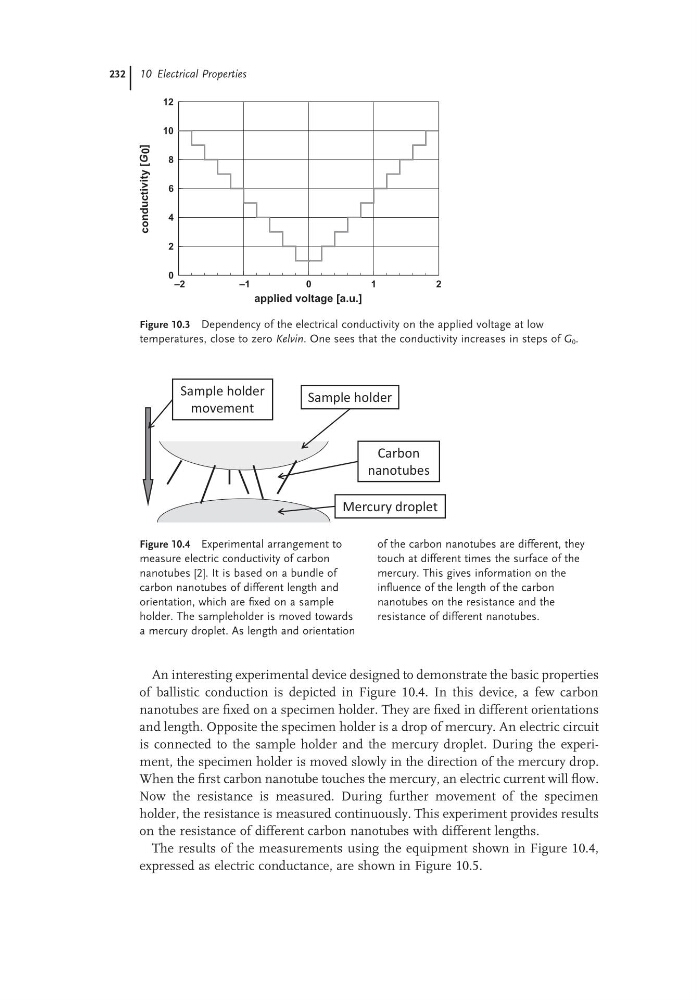
Figure 10.3 Dependency of the electrical conductivity on the applied voltage at low
temperatures, close to zero Kelvin. One sees that the conductivity increases in steps of G 0 .
–2
–1
0
1
2
applied voltage [a.u.]
0
2
4
6
8
10
12
conductivity
[G 0
]
Figure 10.4 Experimental arrangement to
measure electric conductivity of carbon
nanotubes [2]. It is based on a bundle of
carbon nanotubes of different length and
orientation, which are fixed on a sample
holder. The sampleholder is moved towards
a mercury droplet. As length and orientation
of the carbon nanotubes are different, they
touch at different times the surface of the
mercury. This gives information on the
influence of the length of the carbon
nanotubes on the resistance and the
resistance of different nanotubes.
Mercury droplet
Carbon
nanotubes
Sample holder
Sample holder
movement
An interesting experimental device designed to demonstrate the basic properties
of ballistic conduction is depicted in Figure 10.4. In this device, a few carbon
nanotubes are fixed on a specimen holder. They are fixed in different orientations
and length. Opposite the specimen holder is a drop of mercury. An electric circuit
is connected to the sample holder and the mercury droplet. During the experiment, the specimen holder is moved slowly in the direction of the mercury drop.
When the first carbon nanotube touches the mercury, an electric current will flow.
Now the resistance is measured. During further movement of the specimen
holder, the resistance is measured continuously. This experiment provides results
on the resistance of different carbon nanotubes with different lengths.
The results of the measurements using the equipment shown in Figure 10.4,
expressed as electric conductance, are shown in Figure 10.5.
Figure 10.3 Dependency of the electrical conductivity on the applied voltage at low
temperatures, close to zero Kelvin. One sees that the conductivity increases in steps of G 0 .
–2
–1
0
1
2
applied voltage [a.u.]
0
2
4
6
8
10
12
conductivity
[G 0
]
Figure 10.4 Experimental arrangement to
measure electric conductivity of carbon
nanotubes [2]. It is based on a bundle of
carbon nanotubes of different length and
orientation, which are fixed on a sample
holder. The sampleholder is moved towards
a mercury droplet. As length and orientation
of the carbon nanotubes are different, they
touch at different times the surface of the
mercury. This gives information on the
influence of the length of the carbon
nanotubes on the resistance and the
resistance of different nanotubes.
Mercury droplet
Carbon
nanotubes
Sample holder
Sample holder
movement
An interesting experimental device designed to demonstrate the basic properties
of ballistic conduction is depicted in Figure 10.4. In this device, a few carbon
nanotubes are fixed on a specimen holder. They are fixed in different orientations
and length. Opposite the specimen holder is a drop of mercury. An electric circuit
is connected to the sample holder and the mercury droplet. During the experiment, the specimen holder is moved slowly in the direction of the mercury drop.
When the first carbon nanotube touches the mercury, an electric current will flow.
Now the resistance is measured. During further movement of the specimen
holder, the resistance is measured continuously. This experiment provides results
on the resistance of different carbon nanotubes with different lengths.
The results of the measurements using the equipment shown in Figure 10.4,
expressed as electric conductance, are shown in Figure 10.5.