

216 9 Optical Properties
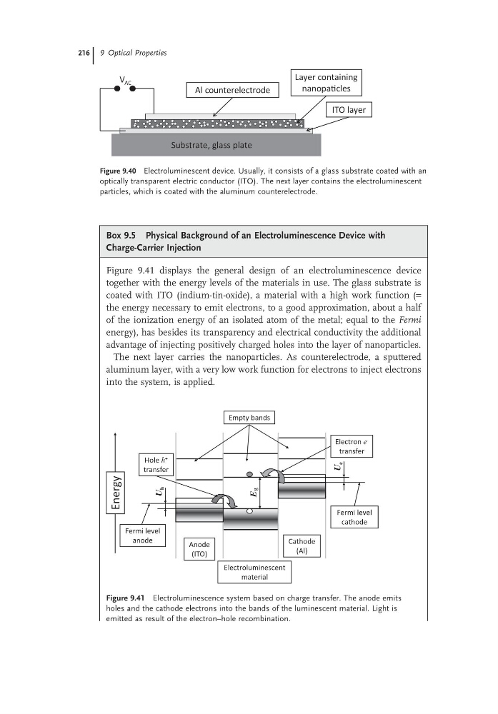
Figure 9.40 Electroluminescent device. Usually, it consists of a glass substrate coated with an
optically transparent electric conductor (ITO). The next layer contains the electroluminescent
particles, which is coated with the aluminum counterelectrode.
V AC
Substrate, glass plate
ITO layer
Layer containing
nanopaƟcles
Al counterelectrode
Box 9.5 Physical Background of an Electroluminescence Device with
Charge-Carrier Injection
Figure 9.41 displays the general design of an electroluminescence device
together with the energy levels of the materials in use. The glass substrate is
coated with ITO (indium-tin-oxide), a material with a high work function (=
the energy necessary to emit electrons, to a good approximation, about a half
of the ionization energy of an isolated atom of the metal; equal to the Fermi
energy), has besides its transparency and electrical conductivity the additional
advantage of injecting positively charged holes into the layer of nanoparticles.
The next layer carries the nanoparticles. As counterelectrode, a sputtered
aluminum layer, with a very low work function for electrons to inject electrons
into the system, is applied.
Figure 9.41 Electroluminescence system based on charge transfer. The anode emits
holes and the cathode electrons into the bands of the luminescent material. Light is
emitted as result of the electron–hole recombination.
Anode
(ITO)
Electroluminescent
material
Cathode
(Al)
Empty bands
Eg
U
e
U
h
Fermi level
anode
Fermi level
cathode
Hole h +
transfer
Electron e -
transfer
Energy
Figure 9.40 Electroluminescent device. Usually, it consists of a glass substrate coated with an
optically transparent electric conductor (ITO). The next layer contains the electroluminescent
particles, which is coated with the aluminum counterelectrode.
V AC
Substrate, glass plate
ITO layer
Layer containing
nanopaƟcles
Al counterelectrode
Box 9.5 Physical Background of an Electroluminescence Device with
Charge-Carrier Injection
Figure 9.41 displays the general design of an electroluminescence device
together with the energy levels of the materials in use. The glass substrate is
coated with ITO (indium-tin-oxide), a material with a high work function (=
the energy necessary to emit electrons, to a good approximation, about a half
of the ionization energy of an isolated atom of the metal; equal to the Fermi
energy), has besides its transparency and electrical conductivity the additional
advantage of injecting positively charged holes into the layer of nanoparticles.
The next layer carries the nanoparticles. As counterelectrode, a sputtered
aluminum layer, with a very low work function for electrons to inject electrons
into the system, is applied.
Figure 9.41 Electroluminescence system based on charge transfer. The anode emits
holes and the cathode electrons into the bands of the luminescent material. Light is
emitted as result of the electron–hole recombination.
Anode
(ITO)
Electroluminescent
material
Cathode
(Al)
Empty bands
Eg
U
e
U
h
Fermi level
anode
Fermi level
cathode
Hole h +
transfer
Electron e -
transfer
Energy