

94 5 One- and Two-Dimensional Nanoparticles
significantly reduced; therefore, electron microscopy of these endcaps is very
difficult.
There are many applications exploiting the electrical conductivity and the high
mechanical strength. The unique combination of small diameter and mechanical
stiffness make carbon nanotubes ideal tips for scanning force or scanning tunnel
microscopes. Furthermore, carbon nanotubes are applied in polymer-bond composites of high strength.
Box 5.7 Geometry of Graphene and Carbon Nanotubes
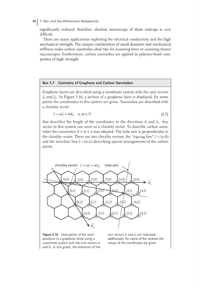
Graphene layers are described using a coordinate system with the unit vectors
e 1 and
e 21 . In Figure 5.16, a section of a graphene layer is displayed, for some
points the coordinates in this system are given. Nanotubes are described with
a chirality vector
»
c ne me n m
=
+
∈
1
2 , ,
(5.7)
that describes the length of the coordinates in the directions
e 1 and
e 21 . Any
vector in this system can serve as a chirality vector. To describe carbon nanotubes the convention 0 ≤ m ≤ n was adopted. The tube axis is perpendicular to
the chirality vector. There are two chirality vectors, the “zig-zag line”
c n
= ( )
,0
and the armchair line
c n n
= ( )
, describing special arrangements of the carbon
atoms.
Figure 5.16 Description of the atom
positions in a graphene sheet using a
coordinate system with the unit vectors
e 1
and
e 2 . In this graph, the directions of the
( )
0
0,
( )
2
4,
( )
0
1,
( )
0
3,
( )
0
2,
( )
0
4,
( )
0
5,
( )
2
3,
( )
2
2,
( )
1
1,
( )
1
2,
( )
1
3,
( )
1
4,
( )
1
4,
( )
3
3,
( )
3
4,
( )
3
2,
( )
2
1,
( )
1
0,
( )
2
0,
( )
3
0,
( )
3
1,
tube axis
chirality vector
1
e
2
e
2
1
e
m
e
n
c
+
=
unit vectors
e 1 and
e 2 are indicated;
additionally, for some of the vertices the
values of the coordinates are given.
significantly reduced; therefore, electron microscopy of these endcaps is very
difficult.
There are many applications exploiting the electrical conductivity and the high
mechanical strength. The unique combination of small diameter and mechanical
stiffness make carbon nanotubes ideal tips for scanning force or scanning tunnel
microscopes. Furthermore, carbon nanotubes are applied in polymer-bond composites of high strength.
Box 5.7 Geometry of Graphene and Carbon Nanotubes
Graphene layers are described using a coordinate system with the unit vectors
e 1 and
e 21 . In Figure 5.16, a section of a graphene layer is displayed, for some
points the coordinates in this system are given. Nanotubes are described with
a chirality vector
»
c ne me n m
=
+
∈
1
2 , ,
(5.7)
that describes the length of the coordinates in the directions
e 1 and
e 21 . Any
vector in this system can serve as a chirality vector. To describe carbon nanotubes the convention 0 ≤ m ≤ n was adopted. The tube axis is perpendicular to
the chirality vector. There are two chirality vectors, the “zig-zag line”
c n
= ( )
,0
and the armchair line
c n n
= ( )
, describing special arrangements of the carbon
atoms.
Figure 5.16 Description of the atom
positions in a graphene sheet using a
coordinate system with the unit vectors
e 1
and
e 2 . In this graph, the directions of the
( )
0
0,
( )
2
4,
( )
0
1,
( )
0
3,
( )
0
2,
( )
0
4,
( )
0
5,
( )
2
3,
( )
2
2,
( )
1
1,
( )
1
2,
( )
1
3,
( )
1
4,
( )
1
4,
( )
3
3,
( )
3
4,
( )
3
2,
( )
2
1,
( )
1
0,
( )
2
0,
( )
3
0,
( )
3
1,
tube axis
chirality vector
1
e
2
e
2
1
e
m
e
n
c
+
=
unit vectors
e 1 and
e 2 are indicated;
additionally, for some of the vertices the
values of the coordinates are given.