

18. At the end of the process, let the part cool down and then pour
some ethanol at its base.
19. After some time (i.e., a couple of minutes), the part can be
detached.
20. Dry the scaffold with nitrogen and store vacuum-sealed in a
dark and dry place.
3.3.3 Bioextrusion
Manufacturing with a SysEng BioScaffolder (Fig. 3a) equipped
with a G22 encapsulation needle (Fig. 4a right) is described as an
example of a screw-based AM system. The following steps need to
be followed for preparation of the system (brief visual instructions
can be found in Supplementary Video 3):
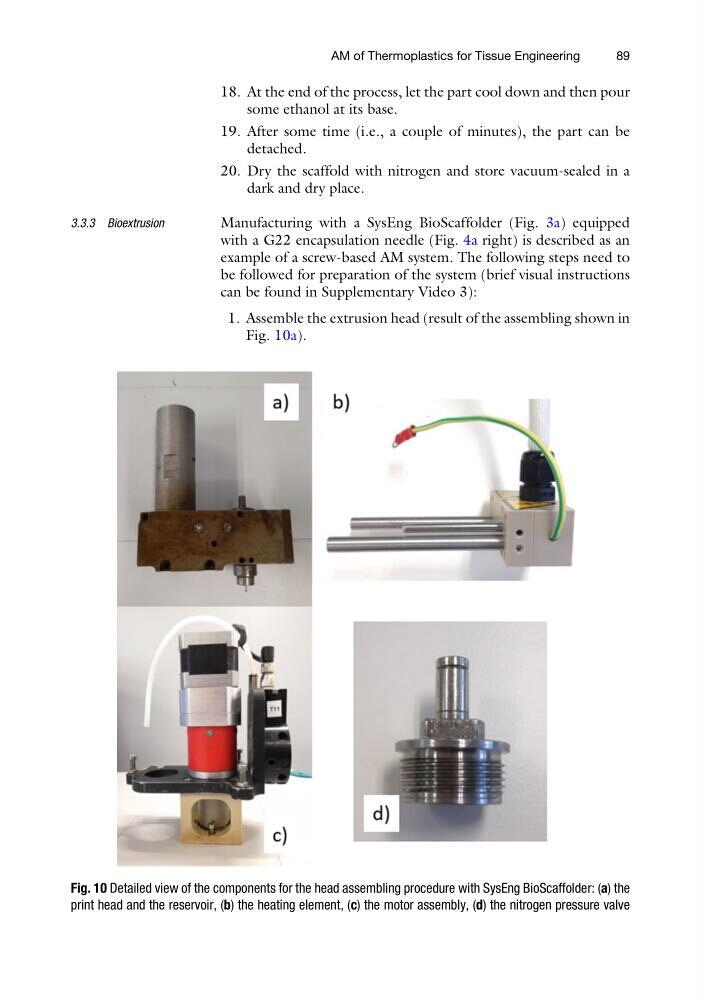
1. Assemble the extrusion head (result of the assembling shown in
Fig. 10a).
Fig. 10 Detailed view of the components for the head assembling procedure with SysEng BioScaffolder: (a) the
print head and the reservoir, (b) the heating element, (c) the motor assembly, (d) the nitrogen pressure valve
AM of Thermoplastics for Tissue Engineering
89
some ethanol at its base.
19. After some time (i.e., a couple of minutes), the part can be
detached.
20. Dry the scaffold with nitrogen and store vacuum-sealed in a
dark and dry place.
3.3.3 Bioextrusion
Manufacturing with a SysEng BioScaffolder (Fig. 3a) equipped
with a G22 encapsulation needle (Fig. 4a right) is described as an
example of a screw-based AM system. The following steps need to
be followed for preparation of the system (brief visual instructions
can be found in Supplementary Video 3):
1. Assemble the extrusion head (result of the assembling shown in
Fig. 10a).
Fig. 10 Detailed view of the components for the head assembling procedure with SysEng BioScaffolder: (a) the
print head and the reservoir, (b) the heating element, (c) the motor assembly, (d) the nitrogen pressure valve
AM of Thermoplastics for Tissue Engineering
89