

place the syringe in the oven with the tip facing up for at least
4 h at 100
C. This allows the PCL pellets to melt and flow to
the bottom of the syringe leaving any air to rise to the top.
2. Gently push on the piston to expel the air bubbles through
the tip.
3. Load the polymer-filled syringe into the MEW machine, and
adjust the distance between the tip of the needle (spinneret)
and the collector to 7 mm.
4. Wipe the collector with acetone/ethanol to remove any dust
particles/contaminants.
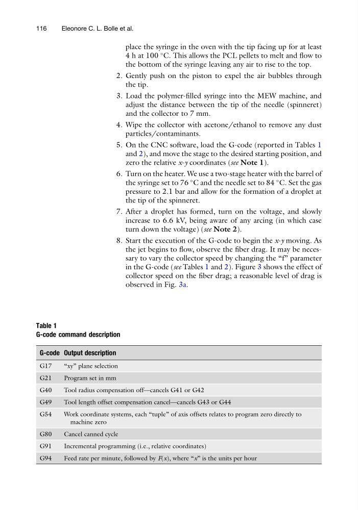
5. On the CNC software, load the G-code (reported in Tables 1
and 2), and move the stage to the desired starting position, and
zero the relative x-y coordinates (see Note 1).
6. Turn on the heater. We use a two-stage heater with the barrel of
the syringe set to 76
C and the needle set to 84
C. Set the gas
pressure to 2.1 bar and allow for the formation of a droplet at
the tip of the spinneret.
7. After a droplet has formed, turn on the voltage, and slowly
increase to 6.6 kV, being aware of any arcing (in which case
turn down the voltage) (see Note 2).
8. Start the execution of the G-code to begin the x-y moving. As
the jet begins to flow, observe the fiber drag. It may be necessary to vary the collector speed by changing the “f” parameter
in the G-code (see Tables 1 and 2). Figure 3 shows the effect of
collector speed on the fiber drag; a reasonable level of drag is
observed in Fig. 3a.
Table 1
G-code command description
G-code Output description
G17
“xy” plane selection
G21
Program set in mm
G40
Tool radius compensation off—cancels G41 or G42
G49
Tool length offset compensation cancel—cancels G43 or G44
G54
Work coordinate systems, each “tuple” of axis offsets relates to program zero directly to
machine zero
G80
Cancel canned cycle
G91
Incremental programming (i.e., relative coordinates)
G94
Feed rate per minute, followed by F(x), where “x” is the units per hour
116
Eleonore C. L. Bolle et al.
4 h at 100
C. This allows the PCL pellets to melt and flow to
the bottom of the syringe leaving any air to rise to the top.
2. Gently push on the piston to expel the air bubbles through
the tip.
3. Load the polymer-filled syringe into the MEW machine, and
adjust the distance between the tip of the needle (spinneret)
and the collector to 7 mm.
4. Wipe the collector with acetone/ethanol to remove any dust
particles/contaminants.
5. On the CNC software, load the G-code (reported in Tables 1
and 2), and move the stage to the desired starting position, and
zero the relative x-y coordinates (see Note 1).
6. Turn on the heater. We use a two-stage heater with the barrel of
the syringe set to 76
C and the needle set to 84
C. Set the gas
pressure to 2.1 bar and allow for the formation of a droplet at
the tip of the spinneret.
7. After a droplet has formed, turn on the voltage, and slowly
increase to 6.6 kV, being aware of any arcing (in which case
turn down the voltage) (see Note 2).
8. Start the execution of the G-code to begin the x-y moving. As
the jet begins to flow, observe the fiber drag. It may be necessary to vary the collector speed by changing the “f” parameter
in the G-code (see Tables 1 and 2). Figure 3 shows the effect of
collector speed on the fiber drag; a reasonable level of drag is
observed in Fig. 3a.
Table 1
G-code command description
G-code Output description
G17
“xy” plane selection
G21
Program set in mm
G40
Tool radius compensation off—cancels G41 or G42
G49
Tool length offset compensation cancel—cancels G43 or G44
G54
Work coordinate systems, each “tuple” of axis offsets relates to program zero directly to
machine zero
G80
Cancel canned cycle
G91
Incremental programming (i.e., relative coordinates)
G94
Feed rate per minute, followed by F(x), where “x” is the units per hour
116
Eleonore C. L. Bolle et al.