

Structure and Properties of B 4 C Coatings Obtained …
53
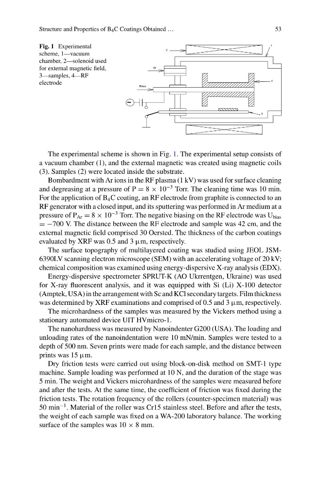
Fig. 1 Experimental
scheme, 1—vacuum
chamber, 2—solenoid used
for external magnetic field,
3—samples, 4—RF
electrode
Ar
Вода
1
2
3
4
~
The experimental scheme is shown in Fig. 1. The experimental setup consists of
a vacuum chamber (1), and the external magnetic was created using magnetic coils
(3). Samples (2) were located inside the substrate.
Bombardment with Ar ions in the RF plasma (1 kV) was used for surface cleaning
and degreasing at a pressure of P = 8 × 10
−3 Torr. The cleaning time was 10 min.
For the application of B 4 C coating, an RF electrode from graphite is connected to an
RF generator with a closed input, and its sputtering was performed in Ar medium at a
pressure of P Ar = 8 × 10
−3 Torr. The negative biasing on the RF electrode was U bias
= −700 V. The distance between the RF electrode and sample was 42 cm, and the
external magnetic field comprised 30 Oersted. The thickness of the carbon coatings
evaluated by XRF was 0.5 and 3 µm, respectively.
The surface topography of multilayered coating was studied using JEOL JSM6390LV scanning electron microscope (SEM) with an accelerating voltage of 20 kV;
chemical composition was examined using energy-dispersive X-ray analysis (EDX).
Energy-dispersive spectrometer SPRUT-K (AO Ukrrentgen, Ukraine) was used
for X-ray fluorescent analysis, and it was equipped with Si (Li) X-100 detector
(Amptek, USA) in the arrangement with Sc and KCl secondary targets. Film thickness
was determined by XRF examinations and comprised of 0.5 and 3 µm, respectively.
The microhardness of the samples was measured by the Vickers method using a
stationary automated device UIT HVmicro-1.
The nanohardness was measured by Nanoindenter G200 (USA). The loading and
unloading rates of the nanoindentation were 10 mN/min. Samples were tested to a
depth of 500 nm. Seven prints were made for each sample, and the distance between
prints was 15 µm.
Dry friction tests were carried out using block-on-disk method on SMT-1 type
machine. Sample loading was performed at 10 N, and the duration of the stage was
5 min. The weight and Vickers microhardness of the samples were measured before
and after the tests. At the same time, the coefficient of friction was fixed during the
friction tests. The rotation frequency of the rollers (counter-specimen material) was
50 min
−1 . Material of the roller was Cr15 stainless steel. Before and after the tests,
the weight of each sample was fixed on a WA-200 laboratory balance. The working
surface of the samples was 10 × 8 mm.
53
Fig. 1 Experimental
scheme, 1—vacuum
chamber, 2—solenoid used
for external magnetic field,
3—samples, 4—RF
electrode
Ar
Вода
1
2
3
4
~
The experimental scheme is shown in Fig. 1. The experimental setup consists of
a vacuum chamber (1), and the external magnetic was created using magnetic coils
(3). Samples (2) were located inside the substrate.
Bombardment with Ar ions in the RF plasma (1 kV) was used for surface cleaning
and degreasing at a pressure of P = 8 × 10
−3 Torr. The cleaning time was 10 min.
For the application of B 4 C coating, an RF electrode from graphite is connected to an
RF generator with a closed input, and its sputtering was performed in Ar medium at a
pressure of P Ar = 8 × 10
−3 Torr. The negative biasing on the RF electrode was U bias
= −700 V. The distance between the RF electrode and sample was 42 cm, and the
external magnetic field comprised 30 Oersted. The thickness of the carbon coatings
evaluated by XRF was 0.5 and 3 µm, respectively.
The surface topography of multilayered coating was studied using JEOL JSM6390LV scanning electron microscope (SEM) with an accelerating voltage of 20 kV;
chemical composition was examined using energy-dispersive X-ray analysis (EDX).
Energy-dispersive spectrometer SPRUT-K (AO Ukrrentgen, Ukraine) was used
for X-ray fluorescent analysis, and it was equipped with Si (Li) X-100 detector
(Amptek, USA) in the arrangement with Sc and KCl secondary targets. Film thickness
was determined by XRF examinations and comprised of 0.5 and 3 µm, respectively.
The microhardness of the samples was measured by the Vickers method using a
stationary automated device UIT HVmicro-1.
The nanohardness was measured by Nanoindenter G200 (USA). The loading and
unloading rates of the nanoindentation were 10 mN/min. Samples were tested to a
depth of 500 nm. Seven prints were made for each sample, and the distance between
prints was 15 µm.
Dry friction tests were carried out using block-on-disk method on SMT-1 type
machine. Sample loading was performed at 10 N, and the duration of the stage was
5 min. The weight and Vickers microhardness of the samples were measured before
and after the tests. At the same time, the coefficient of friction was fixed during the
friction tests. The rotation frequency of the rollers (counter-specimen material) was
50 min
−1 . Material of the roller was Cr15 stainless steel. Before and after the tests,
the weight of each sample was fixed on a WA-200 laboratory balance. The working
surface of the samples was 10 × 8 mm.