

706
A. E. Stetsko and Y. T. Stetsko
Hµ100,MPa
L,µm
0
2000
4000
6000
8000
10000
12000
14000
16000
18000
20000
22000
100 200
300 400 500 600 700 800
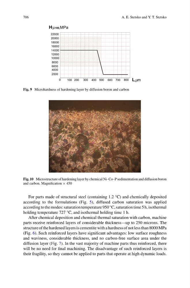
Fig. 9 Microhardness of hardening layer by diffusion boron and carbon
Fig. 10 Microstructure of hardening layer by chemical Ni–Co–P sedimentation and diffusion boron
and carbon. Magnification × 450
For parts made of structural steel (containing 1.2 °C) and chemically deposited
according to the formulations (Fig. 5), diffused carbon saturation was applied
according to the modes: saturation temperature 950 °C, saturation time 5 h, isothermal
holding temperature 727 °C, and isothermal holding time 1 h.
After chemical deposition and chemical thermal saturation with carbon, machine
parts receive reinforced layers of considerable thickness—up to 250 microns. The
structure of the hardened layers is cementite with a hardness of not less than 8000 MPa
(Fig. 6). Such reinforced layers have significant advantages: low surface roughness
and waviness, considerable thickness, and no carbon-free surface area under the
diffusion layer (Fig. 7). In the vast majority of machine parts thus reinforced, there
will be no need for final machining. The disadvantage of such reinforced layers is
their fragility, so they cannot be applied to parts that operate at high dynamic loads.