

384
L. L. Vovchenko et al.
24.3.3 Dielectric Properties of CMs GNP/CNT/L285
The dielectric constant ε
r is a measure of the amount of energy stored, and the
dielectric loss ε
r is a measure of the amount of energy dissipated in the dielectric
material under an applied electric field, and complex dielectric constant can be
presented as ε ∗
r = ε
r − i · ε
r [20].
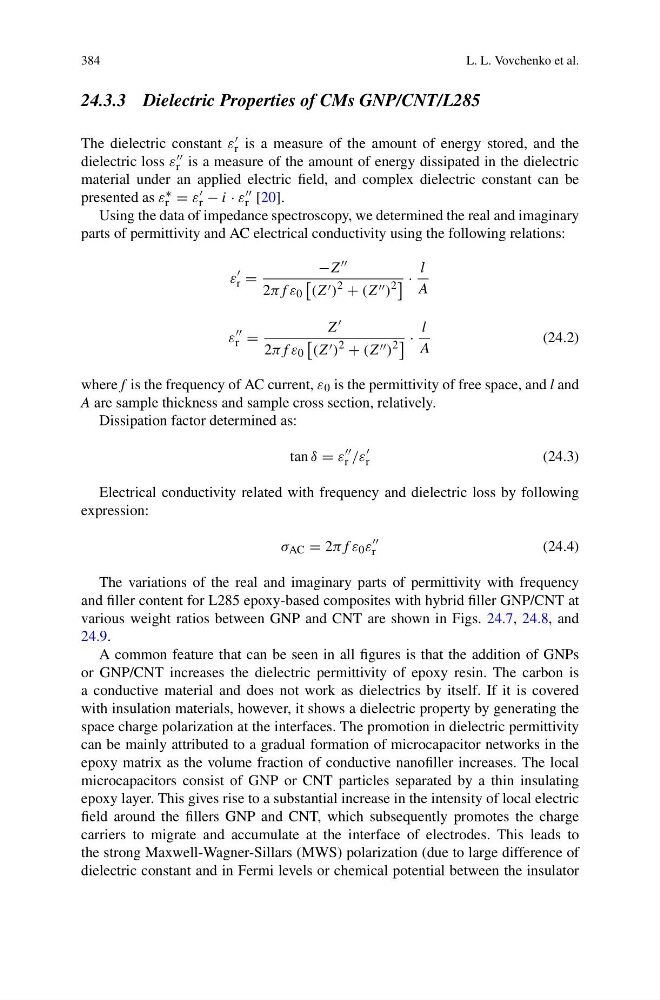
Using the data of impedance spectroscopy, we determined the real and imaginary
parts of permittivity and AC electrical conductivity using the following relations:
ε
r =
−Z
2πf ε 0
(Z )
2
+ (Z )
2
·
l
A
ε
r =
Z
2πf ε 0
(Z )
2
+ (Z )
2
·
l
A
(24.2)
where f is the frequency of AC current, ε 0 is the permittivity of free space, and l and
A are sample thickness and sample cross section, relatively.
Dissipation factor determined as:
tan δ = ε
r /ε
r
(24.3)
Electrical conductivity related with frequency and dielectric loss by following
expression:
σ AC = 2πf ε 0 ε
r
(24.4)
The variations of the real and imaginary parts of permittivity with frequency
and filler content for L285 epoxy-based composites with hybrid filler GNP/CNT at
various weight ratios between GNP and CNT are shown in Figs. 24.7, 24.8, and
24.9.
A common feature that can be seen in all figures is that the addition of GNPs
or GNP/CNT increases the dielectric permittivity of epoxy resin. The carbon is
a conductive material and does not work as dielectrics by itself. If it is covered
with insulation materials, however, it shows a dielectric property by generating the
space charge polarization at the interfaces. The promotion in dielectric permittivity
can be mainly attributed to a gradual formation of microcapacitor networks in the
epoxy matrix as the volume fraction of conductive nanofiller increases. The local
microcapacitors consist of GNP or CNT particles separated by a thin insulating
epoxy layer. This gives rise to a substantial increase in the intensity of local electric
field around the fillers GNP and CNT, which subsequently promotes the charge
carriers to migrate and accumulate at the interface of electrodes. This leads to
the strong Maxwell-Wagner-Sillars (MWS) polarization (due to large difference of
dielectric constant and in Fermi levels or chemical potential between the insulator
L. L. Vovchenko et al.
24.3.3 Dielectric Properties of CMs GNP/CNT/L285
The dielectric constant ε
r is a measure of the amount of energy stored, and the
dielectric loss ε
r is a measure of the amount of energy dissipated in the dielectric
material under an applied electric field, and complex dielectric constant can be
presented as ε ∗
r = ε
r − i · ε
r [20].
Using the data of impedance spectroscopy, we determined the real and imaginary
parts of permittivity and AC electrical conductivity using the following relations:
ε
r =
−Z
2πf ε 0
(Z )
2
+ (Z )
2
·
l
A
ε
r =
Z
2πf ε 0
(Z )
2
+ (Z )
2
·
l
A
(24.2)
where f is the frequency of AC current, ε 0 is the permittivity of free space, and l and
A are sample thickness and sample cross section, relatively.
Dissipation factor determined as:
tan δ = ε
r /ε
r
(24.3)
Electrical conductivity related with frequency and dielectric loss by following
expression:
σ AC = 2πf ε 0 ε
r
(24.4)
The variations of the real and imaginary parts of permittivity with frequency
and filler content for L285 epoxy-based composites with hybrid filler GNP/CNT at
various weight ratios between GNP and CNT are shown in Figs. 24.7, 24.8, and
24.9.
A common feature that can be seen in all figures is that the addition of GNPs
or GNP/CNT increases the dielectric permittivity of epoxy resin. The carbon is
a conductive material and does not work as dielectrics by itself. If it is covered
with insulation materials, however, it shows a dielectric property by generating the
space charge polarization at the interfaces. The promotion in dielectric permittivity
can be mainly attributed to a gradual formation of microcapacitor networks in the
epoxy matrix as the volume fraction of conductive nanofiller increases. The local
microcapacitors consist of GNP or CNT particles separated by a thin insulating
epoxy layer. This gives rise to a substantial increase in the intensity of local electric
field around the fillers GNP and CNT, which subsequently promotes the charge
carriers to migrate and accumulate at the interface of electrodes. This leads to
the strong Maxwell-Wagner-Sillars (MWS) polarization (due to large difference of
dielectric constant and in Fermi levels or chemical potential between the insulator