

24 Dielectric Properties and AC Conductivity of Epoxy/Hybrid Nanocarbon. . .
381
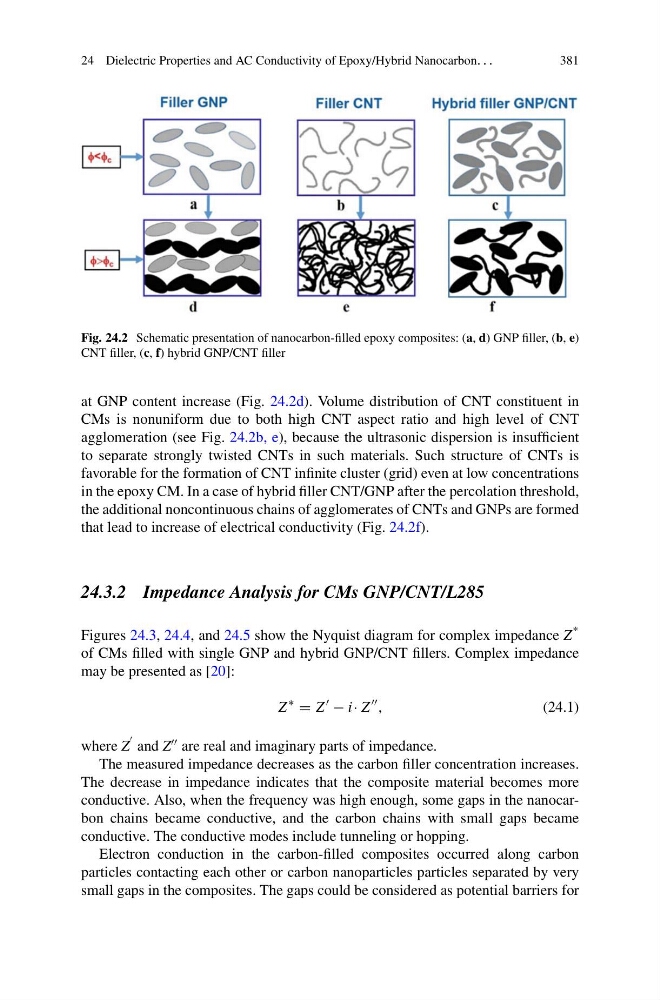
Fig. 24.2 Schematic presentation of nanocarbon-filled epoxy composites: (a, d) GNP filler, (b, e)
CNT filler, (c, f) hybrid GNP/CNT filler
at GNP content increase (Fig. 24.2d). Volume distribution of CNT constituent in
CMs is nonuniform due to both high CNT aspect ratio and high level of CNT
agglomeration (see Fig. 24.2b, e), because the ultrasonic dispersion is insufficient
to separate strongly twisted CNTs in such materials. Such structure of CNTs is
favorable for the formation of CNT infinite cluster (grid) even at low concentrations
in the epoxy CM. In a case of hybrid filler CNT/GNP after the percolation threshold,
the additional noncontinuous chains of agglomerates of CNTs and GNPs are formed
that lead to increase of electrical conductivity (Fig. 24.2f).
24.3.2 Impedance Analysis for CMs GNP/CNT/L285
Figures 24.3, 24.4, and 24.5 show the Nyquist diagram for complex impedance Z *
of CMs filled with single GNP and hybrid GNP/CNT fillers. Complex impedance
may be presented as [20]:
Z
∗
= Z
− i· Z
,
(24.1)
where Z
and Z are real and imaginary parts of impedance.
The measured impedance decreases as the carbon filler concentration increases.
The decrease in impedance indicates that the composite material becomes more
conductive. Also, when the frequency was high enough, some gaps in the nanocarbon chains became conductive, and the carbon chains with small gaps became
conductive. The conductive modes include tunneling or hopping.
Electron conduction in the carbon-filled composites occurred along carbon
particles contacting each other or carbon nanoparticles particles separated by very
small gaps in the composites. The gaps could be considered as potential barriers for
381
Fig. 24.2 Schematic presentation of nanocarbon-filled epoxy composites: (a, d) GNP filler, (b, e)
CNT filler, (c, f) hybrid GNP/CNT filler
at GNP content increase (Fig. 24.2d). Volume distribution of CNT constituent in
CMs is nonuniform due to both high CNT aspect ratio and high level of CNT
agglomeration (see Fig. 24.2b, e), because the ultrasonic dispersion is insufficient
to separate strongly twisted CNTs in such materials. Such structure of CNTs is
favorable for the formation of CNT infinite cluster (grid) even at low concentrations
in the epoxy CM. In a case of hybrid filler CNT/GNP after the percolation threshold,
the additional noncontinuous chains of agglomerates of CNTs and GNPs are formed
that lead to increase of electrical conductivity (Fig. 24.2f).
24.3.2 Impedance Analysis for CMs GNP/CNT/L285
Figures 24.3, 24.4, and 24.5 show the Nyquist diagram for complex impedance Z *
of CMs filled with single GNP and hybrid GNP/CNT fillers. Complex impedance
may be presented as [20]:
Z
∗
= Z
− i· Z
,
(24.1)
where Z
and Z are real and imaginary parts of impedance.
The measured impedance decreases as the carbon filler concentration increases.
The decrease in impedance indicates that the composite material becomes more
conductive. Also, when the frequency was high enough, some gaps in the nanocarbon chains became conductive, and the carbon chains with small gaps became
conductive. The conductive modes include tunneling or hopping.
Electron conduction in the carbon-filled composites occurred along carbon
particles contacting each other or carbon nanoparticles particles separated by very
small gaps in the composites. The gaps could be considered as potential barriers for