

47
Analysis and Design of a Bionic Fitness Cycle
START
Initialize the variant ω1,
resistance level
Delay 2s &
calculate the speed ω
Yes
No
No
Yes
ω > ω 1
resistance_level >
opt_level
resistance_level++
resistance_level– –
resistance_level
= opt_level
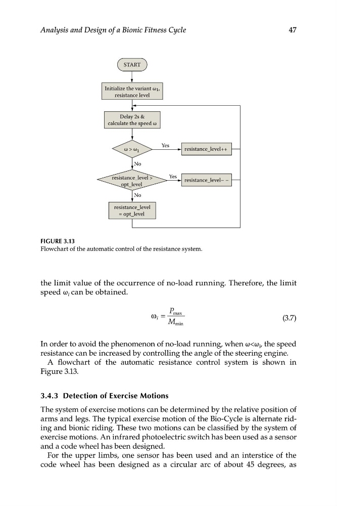
FIGURE 3.13
Flowchart of the automatic control of the resistance system.
the limit value of the occurrence of no-load running. Therefore, the limit
speed ω l can be obtained.
P max
ω l =
(3.7)
M min
In order to avoid the phenomenon of no-load running, when ω<ω l , the speed
resistance can be increased by controlling the angle of the steering engine.
A flowchart of the automatic resistance control system is shown in
Figure 3.13.
3.4.3 Detection of Exercise Motions
The system of exercise motions can be determined by the relative position of
arms and legs. The typical exercise motion of the Bio-Cycle is alternate riding and bionic riding. These two motions can be classified by the system of
exercise motions. An infrared photoelectric switch has been used as a sensor
and a code wheel has been designed.
For the upper limbs, one sensor has been used and an interstice of the
code wheel has been designed as a circular arc of about 45 degrees, as
Analysis and Design of a Bionic Fitness Cycle
START
Initialize the variant ω1,
resistance level
Delay 2s &
calculate the speed ω
Yes
No
No
Yes
ω > ω 1
resistance_level >
opt_level
resistance_level++
resistance_level– –
resistance_level
= opt_level
FIGURE 3.13
Flowchart of the automatic control of the resistance system.
the limit value of the occurrence of no-load running. Therefore, the limit
speed ω l can be obtained.
P max
ω l =
(3.7)
M min
In order to avoid the phenomenon of no-load running, when ω<ω l , the speed
resistance can be increased by controlling the angle of the steering engine.
A flowchart of the automatic resistance control system is shown in
Figure 3.13.
3.4.3 Detection of Exercise Motions
The system of exercise motions can be determined by the relative position of
arms and legs. The typical exercise motion of the Bio-Cycle is alternate riding and bionic riding. These two motions can be classified by the system of
exercise motions. An infrared photoelectric switch has been used as a sensor
and a code wheel has been designed.
For the upper limbs, one sensor has been used and an interstice of the
code wheel has been designed as a circular arc of about 45 degrees, as