

L 2
L 0
L 1
O 2
O 1
θ 2min
L
L 2
L 0
L 1
O 2
O 1
θ 2max
L
(a)
(b)
43
Analysis and Design of a Bionic Fitness Cycle
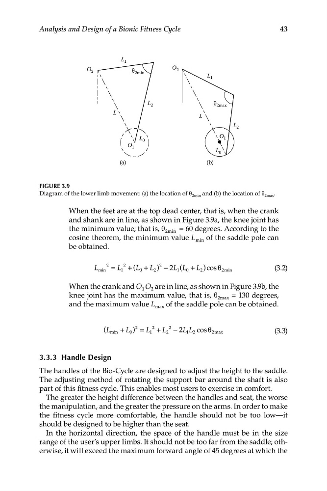
FIGURE 3.9
Diagram of the lower limb movement: (a) the location of θ 2min and (b) the location of θ 2max .
When the feet are at the top dead center, that is, when the crank
and shank are in line, as shown in Figure 3.9a, the knee joint has
the minimum value; that is, θ 2min = 60 degrees. According to the
cosine theorem, the minimum value L min of the saddle pole can
be obtained.
2
2
2
/
= / + (/ + / ) − 2 ( + /
/ /
)c o s θ
(3.2)
min
1
0
2
1
0
2
2min
When the crank and O 1 O 2 are in line, as shown in Figure 3.9b, the
knee joint has the maximum value, that is, θ 2max = 130 degrees,
and the maximum value L max of the saddle pole can be obtained.
2
2
2
min
0
1
2
1 2
2max
(3.3)
(/ + / ) = / + / − 2// c o s θ
3.3.3 Handle Design
The handles of the Bio-Cycle are designed to adjust the height to the saddle.
The adjusting method of rotating the support bar around the shaft is also
part of this fitness cycle. This enables most users to exercise in comfort.
The greater the height difference between the handles and seat, the worse
the manipulation, and the greater the pressure on the arms. In order to make
the fitness cycle more comfortable, the handle should not be too low—it
should be designed to be higher than the seat.
In the horizontal direction, the space of the handle must be in the size
range of the user’s upper limbs. It should not be too far from the saddle; otherwise, it will exceed the maximum forward angle of 45 degrees at which the
L 0
L 1
O 2
O 1
θ 2min
L
L 2
L 0
L 1
O 2
O 1
θ 2max
L
(a)
(b)
43
Analysis and Design of a Bionic Fitness Cycle
FIGURE 3.9
Diagram of the lower limb movement: (a) the location of θ 2min and (b) the location of θ 2max .
When the feet are at the top dead center, that is, when the crank
and shank are in line, as shown in Figure 3.9a, the knee joint has
the minimum value; that is, θ 2min = 60 degrees. According to the
cosine theorem, the minimum value L min of the saddle pole can
be obtained.
2
2
2
/
= / + (/ + / ) − 2 ( + /
/ /
)c o s θ
(3.2)
min
1
0
2
1
0
2
2min
When the crank and O 1 O 2 are in line, as shown in Figure 3.9b, the
knee joint has the maximum value, that is, θ 2max = 130 degrees,
and the maximum value L max of the saddle pole can be obtained.
2
2
2
min
0
1
2
1 2
2max
(3.3)
(/ + / ) = / + / − 2// c o s θ
3.3.3 Handle Design
The handles of the Bio-Cycle are designed to adjust the height to the saddle.
The adjusting method of rotating the support bar around the shaft is also
part of this fitness cycle. This enables most users to exercise in comfort.
The greater the height difference between the handles and seat, the worse
the manipulation, and the greater the pressure on the arms. In order to make
the fitness cycle more comfortable, the handle should not be too low—it
should be designed to be higher than the seat.
In the horizontal direction, the space of the handle must be in the size
range of the user’s upper limbs. It should not be too far from the saddle; otherwise, it will exceed the maximum forward angle of 45 degrees at which the