

284
Biologically Inspired Robotics
Base 1
Base 2
Pulley 1
Pulley 2
Pulley 3
A
X
a 1
a 2
r 1
h 2
h 1
x 1
x 2
r 2
r 3
Y
B
O
θ 1
θ 2
θ 3
β
γ
α
(x, y)
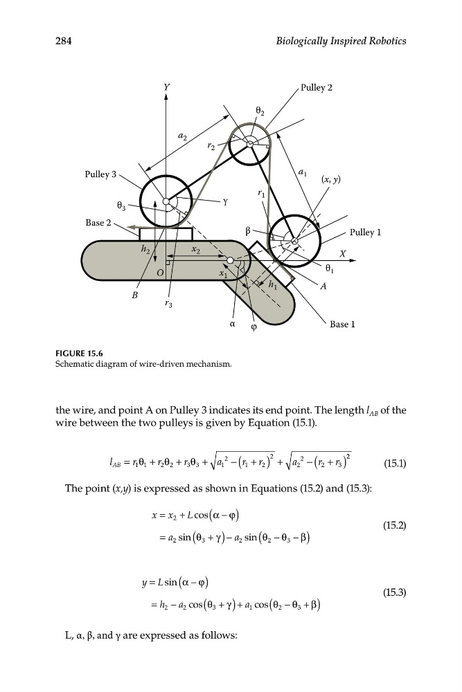
FIGURE 15.6
Schematic diagram of wire-driven mechanism.
the wire, and point A on Pulley 3 indicates its end point. The length l AB of the
wire between the two pulleys is given by Equation (15.1).
2
2 2
l
2
2
AB = r 1 1
θ + r 2 θ 2 + r 3 θ 3 + a 1 − ( r 1 + r 2 ) + a 2 − (r2 + r 3 )
(15.1)
The point (x,y) is expressed as shown in Equations (15.2) and (15.3):
x x
= 2 + Lcos (α ϕ
− )
(15.2)
= a 2 sin (θ3 + γ ) − a 2 sin (θ2 − θ 3 − β)
y L
= sin (α ϕ
− )
(15.3)
= h 2 − a 2 cos(θ 3 + γ ) + a 1 cos (θ 2 − θ 3 + β)
L, α, β, and γ are expressed as follows:
Biologically Inspired Robotics
Base 1
Base 2
Pulley 1
Pulley 2
Pulley 3
A
X
a 1
a 2
r 1
h 2
h 1
x 1
x 2
r 2
r 3
Y
B
O
θ 1
θ 2
θ 3
β
γ
α
(x, y)
FIGURE 15.6
Schematic diagram of wire-driven mechanism.
the wire, and point A on Pulley 3 indicates its end point. The length l AB of the
wire between the two pulleys is given by Equation (15.1).
2
2 2
l
2
2
AB = r 1 1
θ + r 2 θ 2 + r 3 θ 3 + a 1 − ( r 1 + r 2 ) + a 2 − (r2 + r 3 )
(15.1)
The point (x,y) is expressed as shown in Equations (15.2) and (15.3):
x x
= 2 + Lcos (α ϕ
− )
(15.2)
= a 2 sin (θ3 + γ ) − a 2 sin (θ2 − θ 3 − β)
y L
= sin (α ϕ
− )
(15.3)
= h 2 − a 2 cos(θ 3 + γ ) + a 1 cos (θ 2 − θ 3 + β)
L, α, β, and γ are expressed as follows: