

281
Development of Hand Rehabilitation System for Paralysis Patients
the best of our knowledge, this is the most convenient hand rehabilitation
machine available at present. Therefore, we focused on the arm structure
type of machine and endeavored to improve its performance; specifically, we
aimed to increase the range of joint motion and improve the control of finger
movement. To achieve this, we propose a design that combines the closed
four-link mechanism with a wire-driven mechanism.
Our basic design is based on the arm structure type of machine
(Figure 15.2c), which has three joints—one motor joint and two free joints—
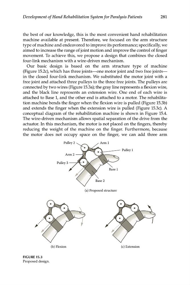
in the closed four-link mechanism. We substituted the motor joint with a
free joint and attached three pulleys to the three free joints. The pulleys are
connected by two wires (Figure 15.3a); the gray line represents a flexion wire,
and the black line represents an extension wire. One end of each wire is
attached to Base 1, and the other end is attached to a motor. The rehabilitation machine bends the finger when the flexion wire is pulled (Figure 15.3b)
and extends the finger when the extension wire is pulled (Figure 15.3c). A
conceptual diagram of the rehabilitation machine is shown in Figure 15.4.
The wire-driven mechanism allows spatial separation of the drive from the
actuator. In this mechanism, the motor is not placed on the fingers, thereby
reducing the weight of the machine on the finger. Furthermore, because
the motor does not occupy space on the finger, we can add three arm
Pulley 1
Pulley 3
Arm 1
Pulley 2
Base 1
Base 2
Arm 2
(a) Proposed structure
(b) Flexion
(c) Extension
FIGURE 15.3
Proposed design.
Development of Hand Rehabilitation System for Paralysis Patients
the best of our knowledge, this is the most convenient hand rehabilitation
machine available at present. Therefore, we focused on the arm structure
type of machine and endeavored to improve its performance; specifically, we
aimed to increase the range of joint motion and improve the control of finger
movement. To achieve this, we propose a design that combines the closed
four-link mechanism with a wire-driven mechanism.
Our basic design is based on the arm structure type of machine
(Figure 15.2c), which has three joints—one motor joint and two free joints—
in the closed four-link mechanism. We substituted the motor joint with a
free joint and attached three pulleys to the three free joints. The pulleys are
connected by two wires (Figure 15.3a); the gray line represents a flexion wire,
and the black line represents an extension wire. One end of each wire is
attached to Base 1, and the other end is attached to a motor. The rehabilitation machine bends the finger when the flexion wire is pulled (Figure 15.3b)
and extends the finger when the extension wire is pulled (Figure 15.3c). A
conceptual diagram of the rehabilitation machine is shown in Figure 15.4.
The wire-driven mechanism allows spatial separation of the drive from the
actuator. In this mechanism, the motor is not placed on the fingers, thereby
reducing the weight of the machine on the finger. Furthermore, because
the motor does not occupy space on the finger, we can add three arm
Pulley 1
Pulley 3
Arm 1
Pulley 2
Base 1
Base 2
Arm 2
(a) Proposed structure
(b) Flexion
(c) Extension
FIGURE 15.3
Proposed design.