

198
Biologically Inspired Robotics
Hybrid
Probes
Brain activity
Signal processing
& control board
sensor
Upper limb assistive device
Monitoring PC
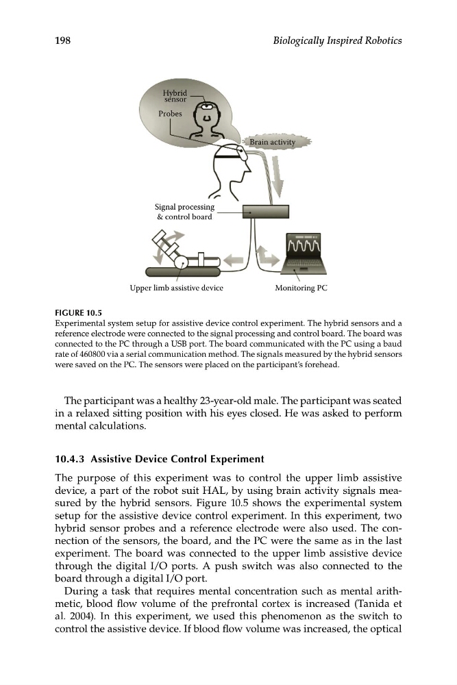
FIGURE 10.5
Experimental system setup for assistive device control experiment. The hybrid sensors and a
reference electrode were connected to the signal processing and control board. The board was
connected to the PC through a USB port. The board communicated with the PC using a baud
rate of 460800 via a serial communication method. The signals measured by the hybrid sensors
were saved on the PC. The sensors were placed on the participant’s forehead.
The participant was a healthy 23-year-old male. The participant was seated
in a relaxed sitting position with his eyes closed. He was asked to perform
mental calculations.
10.4.3 Assistive Device Control Experiment
The purpose of this experiment was to control the upper limb assistive
device, a part of the robot suit HAL, by using brain activity signals measured by the hybrid sensors. Figure 10.5 shows the experimental system
setup for the assistive device control experiment. In this experiment, two
hybrid sensor probes and a reference electrode were also used. The connection of the sensors, the board, and the PC were the same as in the last
experiment. The board was connected to the upper limb assistive device
through the digital I/O ports. A push switch was also connected to the
board through a digital I/O port.
During a task that requires mental concentration such as mental arithmetic, blood flow volume of the prefrontal cortex is increased (Tanida et
al. 2004). In this experiment, we used this phenomenon as the switch to
control the assistive device. If blood flow volume was increased, the optical
Biologically Inspired Robotics
Hybrid
Probes
Brain activity
Signal processing
& control board
sensor
Upper limb assistive device
Monitoring PC
FIGURE 10.5
Experimental system setup for assistive device control experiment. The hybrid sensors and a
reference electrode were connected to the signal processing and control board. The board was
connected to the PC through a USB port. The board communicated with the PC using a baud
rate of 460800 via a serial communication method. The signals measured by the hybrid sensors
were saved on the PC. The sensors were placed on the participant’s forehead.
The participant was a healthy 23-year-old male. The participant was seated
in a relaxed sitting position with his eyes closed. He was asked to perform
mental calculations.
10.4.3 Assistive Device Control Experiment
The purpose of this experiment was to control the upper limb assistive
device, a part of the robot suit HAL, by using brain activity signals measured by the hybrid sensors. Figure 10.5 shows the experimental system
setup for the assistive device control experiment. In this experiment, two
hybrid sensor probes and a reference electrode were also used. The connection of the sensors, the board, and the PC were the same as in the last
experiment. The board was connected to the upper limb assistive device
through the digital I/O ports. A push switch was also connected to the
board through a digital I/O port.
During a task that requires mental concentration such as mental arithmetic, blood flow volume of the prefrontal cortex is increased (Tanida et
al. 2004). In this experiment, we used this phenomenon as the switch to
control the assistive device. If blood flow volume was increased, the optical