

195
Measurement of Brain Activity Using Optical and Electrical Methods
19 mm
19 mm
27 mm
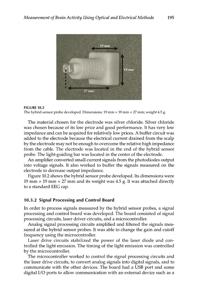
FIGURE 10.2
The hybrid sensor probe developed. Dimensions: 19 mm × 19 mm × 27 mm; weight 4.5 g.
The material chosen for the electrode was silver chloride. Silver chloride
was chosen because of its low price and good performance. It has very low
impedance and can be acquired for relatively low prices. A buffer circuit was
added to the electrode because the electrical current drained from the scalp
by the electrode may not be enough to overcome the relative high impedance
from the cable. The electrode was located in the end of the hybrid sensor
probe. The light-guiding bar was located in the center of the electrode.
An amplifier converted small current signals from the photodiodes output
into voltage signals. It also worked to buffer the signals measured on the
electrode to decrease output impedance.
Figure 10.2 shows the hybrid sensor probe developed. Its dimensions were
19 mm × 19 mm × 27 mm and its weight was 4.5 g. It was attached directly
to a standard EEG cap.
10.3.2 Signal Processing and Control Board
In order to process signals measured by the hybrid sensor probes, a signal
processing and control board was developed. The board consisted of signal
processing circuits, laser driver circuits, and a microcontroller.
Analog signal processing circuits amplified and filtered the signals measured at the hybrid sensor probes. It was able to change the gain and cutoff
frequency using the microcontroller.
Laser drive circuits stabilized the power of the laser diode and controlled the light emission. The timing of the light emission was controlled
by the microcontroller.
The microcontroller worked to control the signal processing circuits and
the laser drive circuits, to convert analog signals into digital signals, and to
communicate with the other devices. The board had a USB port and some
digital I/O ports to allow communication with an external device such as a
Measurement of Brain Activity Using Optical and Electrical Methods
19 mm
19 mm
27 mm
FIGURE 10.2
The hybrid sensor probe developed. Dimensions: 19 mm × 19 mm × 27 mm; weight 4.5 g.
The material chosen for the electrode was silver chloride. Silver chloride
was chosen because of its low price and good performance. It has very low
impedance and can be acquired for relatively low prices. A buffer circuit was
added to the electrode because the electrical current drained from the scalp
by the electrode may not be enough to overcome the relative high impedance
from the cable. The electrode was located in the end of the hybrid sensor
probe. The light-guiding bar was located in the center of the electrode.
An amplifier converted small current signals from the photodiodes output
into voltage signals. It also worked to buffer the signals measured on the
electrode to decrease output impedance.
Figure 10.2 shows the hybrid sensor probe developed. Its dimensions were
19 mm × 19 mm × 27 mm and its weight was 4.5 g. It was attached directly
to a standard EEG cap.
10.3.2 Signal Processing and Control Board
In order to process signals measured by the hybrid sensor probes, a signal
processing and control board was developed. The board consisted of signal
processing circuits, laser driver circuits, and a microcontroller.
Analog signal processing circuits amplified and filtered the signals measured at the hybrid sensor probes. It was able to change the gain and cutoff
frequency using the microcontroller.
Laser drive circuits stabilized the power of the laser diode and controlled the light emission. The timing of the light emission was controlled
by the microcontroller.
The microcontroller worked to control the signal processing circuits and
the laser drive circuits, to convert analog signals into digital signals, and to
communicate with the other devices. The board had a USB port and some
digital I/O ports to allow communication with an external device such as a