

175
Nanorobotic Manipulation for a Single Biological Cell
Si-Ti and W 2 nanoprobes are not a true body of revolution because the needles have a rectangular cross section. However, it has been shown that the
error using models for a non-body of revolution is very small as explained in
detail by Dao et al. (2001) and King (1987).
2
E
F
2
cone = tan α
δ
π
(9.12)
(1 − v
2 )
4
E
F
/2
sp herical =
R
1 2
/ δ
3
(9.13)
3 (1 − v
2 )
E
F cylindrical = 2
aδ
(9.14)
(1 − v
2 )
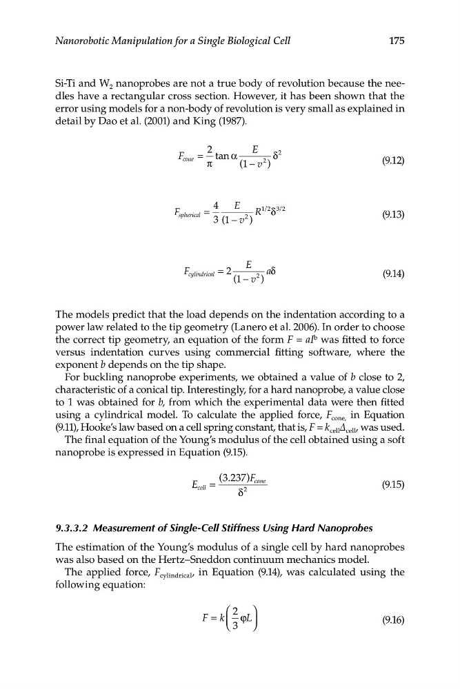
The models predict that the load depends on the indentation according to a
power law related to the tip geometry (Lanero et al. 2006). In order to choose
the correct tip geometry, an equation of the form F = aI b was fitted to force
versus indentation curves using commercial fitting software, where the
exponent b depends on the tip shape.
For buckling nanoprobe experiments, we obtained a value of b close to 2,
characteristic of a conical tip. Interestingly, for a hard nanoprobe, a value close
to 1 was obtained for b, from which the experimental data were then fitted
using a cylindrical model. To calculate the applied force, F cone, in Equation
(9.11), Hooke’s law based on a cell spring constant, that is, F = k cell Δ cell , was used.
The final equation of the Young’s modulus of the cell obtained using a soft
nanoprobe is expressed in Equation (9.15).
( .
3 237)F
E
cone
cell =
(9.15)
δ
2
9.3.3.2 Measurement of Single-Cell Stiffness Using Hard Nanoprobes
The estimation of the Young’s modulus of a single cell by hard nanoprobes
was also based on the Hertz–Sneddon continuum mechanics model.
The applied force, F cylindrical , in Equation (9.14), was calculated using the
following equation:
⎛ 2 ⎞
F k
= ⎜ ϕL ⎟
(9 .16)
⎝ 3 ⎠
Nanorobotic Manipulation for a Single Biological Cell
Si-Ti and W 2 nanoprobes are not a true body of revolution because the needles have a rectangular cross section. However, it has been shown that the
error using models for a non-body of revolution is very small as explained in
detail by Dao et al. (2001) and King (1987).
2
E
F
2
cone = tan α
δ
π
(9.12)
(1 − v
2 )
4
E
F
/2
sp herical =
R
1 2
/ δ
3
(9.13)
3 (1 − v
2 )
E
F cylindrical = 2
aδ
(9.14)
(1 − v
2 )
The models predict that the load depends on the indentation according to a
power law related to the tip geometry (Lanero et al. 2006). In order to choose
the correct tip geometry, an equation of the form F = aI b was fitted to force
versus indentation curves using commercial fitting software, where the
exponent b depends on the tip shape.
For buckling nanoprobe experiments, we obtained a value of b close to 2,
characteristic of a conical tip. Interestingly, for a hard nanoprobe, a value close
to 1 was obtained for b, from which the experimental data were then fitted
using a cylindrical model. To calculate the applied force, F cone, in Equation
(9.11), Hooke’s law based on a cell spring constant, that is, F = k cell Δ cell , was used.
The final equation of the Young’s modulus of the cell obtained using a soft
nanoprobe is expressed in Equation (9.15).
( .
3 237)F
E
cone
cell =
(9.15)
δ
2
9.3.3.2 Measurement of Single-Cell Stiffness Using Hard Nanoprobes
The estimation of the Young’s modulus of a single cell by hard nanoprobes
was also based on the Hertz–Sneddon continuum mechanics model.
The applied force, F cylindrical , in Equation (9.14), was calculated using the
following equation:
⎛ 2 ⎞
F k
= ⎜ ϕL ⎟
(9 .16)
⎝ 3 ⎠