

151
Biomechanical Characterization of Human Red Blood Cells
η
Stretched shape
A B
C
o
ψ
ρ
Initial shape
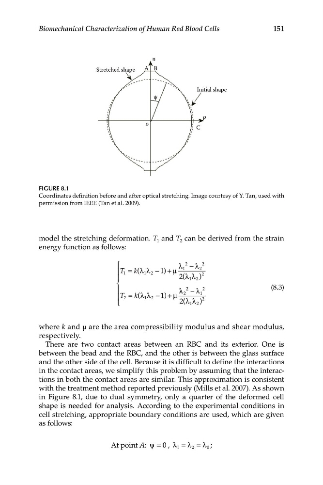
FIGURE 8.1
Coordinates definition before and after optical stretching. Image courtesy of Y. Tan, used with
permission from IEEE (Tan et al. 2009).
model the stretching deformation. T 1 and T 2 can be derived from the strain
energy function as follows:
⎧
λ
2
− λ
2
⎪ T 1 = k(λ λ
1 2 − 1 ) + μ
1
2
⎪
2(λ λ
2
1 2 )
⎨
3)
⎪
λ λ
2
− λ
2
(8.
T 2 =
⎪
k(λ λ 2
2
1
1
− 1) + μ
⎩
2(λ λ
2
1 2 )
where k and μ are the area compressibility modulus and shear modulus,
respectively.
There are two contact areas between an RBC and its exterior. One is
between the bead and the RBC, and the other is between the glass surface
and the other side of the cell. Because it is difficult to define the interactions
in the contact areas, we simplify this problem by assuming that the interactions in both the contact areas are similar. This approximation is consistent
with the treatment method reported previously (Mills et al. 2007). As shown
in Figure 8.1, due to dual symmetry, only a quarter of the deformed cell
shape is needed for analysis. According to the experimental conditions in
cell stretching, appropriate boundary conditions are used, which are given
as follows:
At point A: ψ = , λ 1 = λ 2 = λ 0 ;
Biomechanical Characterization of Human Red Blood Cells
η
Stretched shape
A B
C
o
ψ
ρ
Initial shape
FIGURE 8.1
Coordinates definition before and after optical stretching. Image courtesy of Y. Tan, used with
permission from IEEE (Tan et al. 2009).
model the stretching deformation. T 1 and T 2 can be derived from the strain
energy function as follows:
⎧
λ
2
− λ
2
⎪ T 1 = k(λ λ
1 2 − 1 ) + μ
1
2
⎪
2(λ λ
2
1 2 )
⎨
3)
⎪
λ λ
2
− λ
2
(8.
T 2 =
⎪
k(λ λ 2
2
1
1
− 1) + μ
⎩
2(λ λ
2
1 2 )
where k and μ are the area compressibility modulus and shear modulus,
respectively.
There are two contact areas between an RBC and its exterior. One is
between the bead and the RBC, and the other is between the glass surface
and the other side of the cell. Because it is difficult to define the interactions
in the contact areas, we simplify this problem by assuming that the interactions in both the contact areas are similar. This approximation is consistent
with the treatment method reported previously (Mills et al. 2007). As shown
in Figure 8.1, due to dual symmetry, only a quarter of the deformed cell
shape is needed for analysis. According to the experimental conditions in
cell stretching, appropriate boundary conditions are used, which are given
as follows:
At point A: ψ = , λ 1 = λ 2 = λ 0 ;