

115
Development of a Low-Noise Bio-Inspired Humanoid Robot Neck
F 0 = F in
F n = F out
F j–1
F j
Λ j
F Nj
Motion
f j
f j = μ·F Nj
F j = F j–1 – f j
F j–1
F Nj
F Nj
2 = F j–1
2 + F j
2 + 2F j–1 F j cosΛ j
f j
F Nj
F j
π–Λ i
Λ i in[0, 2π)/π
Cable housing
Cable
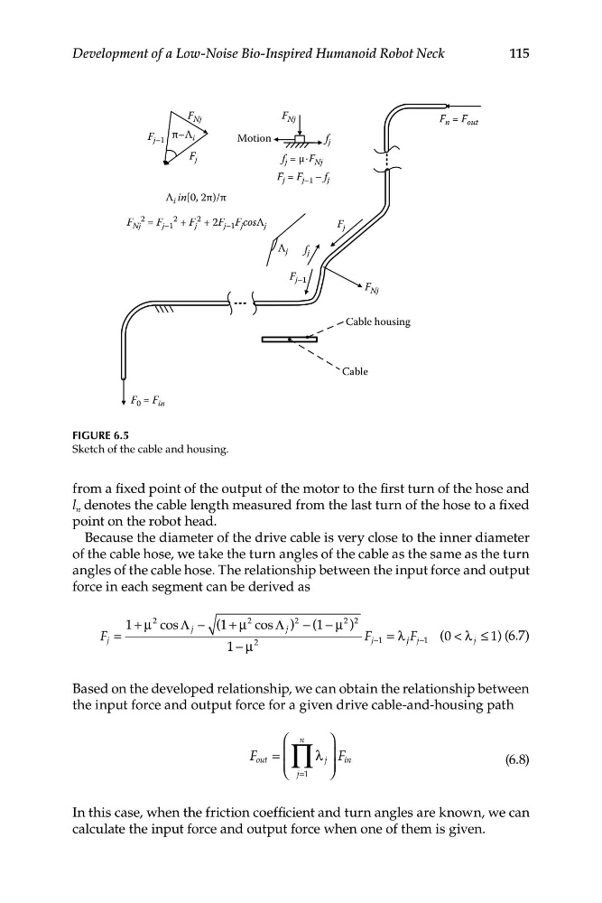
FIGURE 6.5
Sketch of the cable and housing.
from a fixed point of the output of the motor to the first turn of the hose and
l n denotes the cable length measured from the last turn of the hose to a fixed
point on the robot head.
Because the diameter of the drive cable is very close to the inner diameter
of the cable hose, we take the turn angles of the cable as the same as the turn
angles of the cable hose. The relationship between the input force and output
force in each segment can be derived as
1 + μ
2 cos Λ − (1 + μ
2 cos Λ )
2 − (1 − μ
2 )
2
F j =
j
j
2
F j −1 = λ j j j
F −1 (0 < λ j ≤ 1) (6.7)
1 − μ
Based on the developed relationship, we can obtain the relationship between
the input force and output force for a given drive cable-and-housing path
⎛ ∏
n
⎞
F out = ⎜
λ j ⎟ F in
(6.8)
⎜
⎟
⎝ j=
⎠
In this case, when the friction coefficient and turn angles are known, we can
calculate the input force and output force when one of them is given.
Development of a Low-Noise Bio-Inspired Humanoid Robot Neck
F 0 = F in
F n = F out
F j–1
F j
Λ j
F Nj
Motion
f j
f j = μ·F Nj
F j = F j–1 – f j
F j–1
F Nj
F Nj
2 = F j–1
2 + F j
2 + 2F j–1 F j cosΛ j
f j
F Nj
F j
π–Λ i
Λ i in[0, 2π)/π
Cable housing
Cable
FIGURE 6.5
Sketch of the cable and housing.
from a fixed point of the output of the motor to the first turn of the hose and
l n denotes the cable length measured from the last turn of the hose to a fixed
point on the robot head.
Because the diameter of the drive cable is very close to the inner diameter
of the cable hose, we take the turn angles of the cable as the same as the turn
angles of the cable hose. The relationship between the input force and output
force in each segment can be derived as
1 + μ
2 cos Λ − (1 + μ
2 cos Λ )
2 − (1 − μ
2 )
2
F j =
j
j
2
F j −1 = λ j j j
F −1 (0 < λ j ≤ 1) (6.7)
1 − μ
Based on the developed relationship, we can obtain the relationship between
the input force and output force for a given drive cable-and-housing path
⎛ ∏
n
⎞
F out = ⎜
λ j ⎟ F in
(6.8)
⎜
⎟
⎝ j=
⎠
In this case, when the friction coefficient and turn angles are known, we can
calculate the input force and output force when one of them is given.