

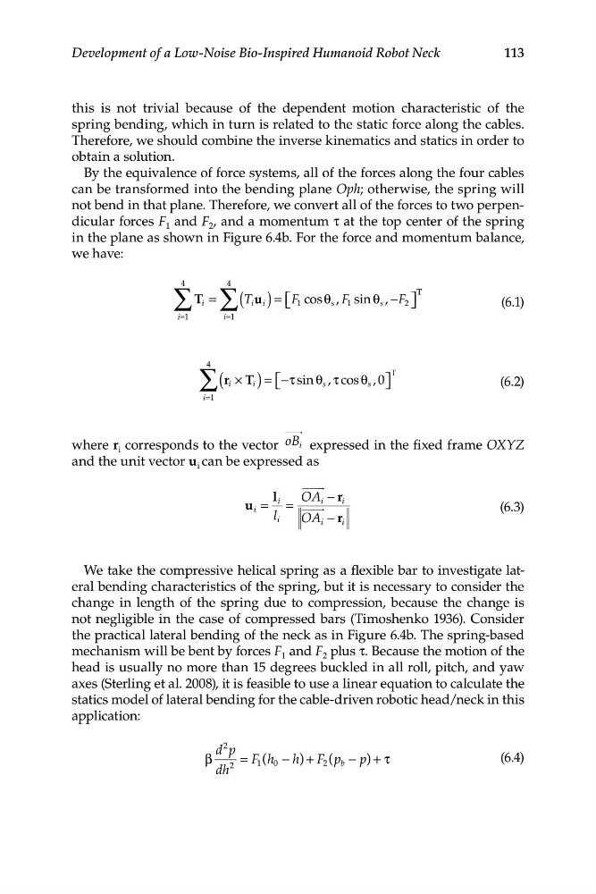
113
Development of a Low-Noise Bio-Inspired Humanoid Robot Neck
this is not trivial because of the dependent motion characteristic of the
spring bending, which in turn is related to the static force along the cables.
Therefore, we should combine the inverse kinematics and statics in order to
obtain a solution.
By the equivalence of force systems, all of the forces along the four cables
can be transformed into the bending plane Oph; otherwise, the spring will
not bend in that plane. Therefore, we convert all of the forces to two perpendicular forces F 1 and F 2 , and a momentum τ at the top center of the spring
in the plane as shown in Figure 6.4b. For the force and momentum balance,
we have:
∑ ∑
4
4
T i =
( T i i
u ) = ⎡
, −F ⎤
T T
⎣ F 1 cos θ s , F 1 sin θ s
2 ⎦
(6.1)
i=1
i=1
∑
4 (ri × T
T
i ) = −
⎡ ⎣ τ sin θ s , τ cos θ s , 0⎤ ⎦
(6.2)
i=1
where r
oB i
i corresponds to the vector
expressed in the fixed frame OXYZ
and the unit vector u i can be expressed as
l
=
i
−
u
r
OA
=
i
i
i
(6.3)
l i
OA i − r i
We take the compressive helical spring as a flexible bar to investigate lateral bending characteristics of the spring, but it is necessary to consider the
change in length of the spring due to compression, because the change is
not negligible in the case of compressed bars (Timoshenko 1936). Consider
the practical lateral bending of the neck as in Figure 6.4b. The spring-based
mechanism will be bent by forces F 1 and F 2 plus τ. Because the motion of the
head is usually no more than 15 degrees buckled in all roll, pitch, and yaw
axes (Sterling et al. 2008), it is feasible to use a linear equation to calculate the
statics model of lateral bending for the cable-driven robotic head/neck in this
application:
d p
2
β
= F h
1 ( 0 − h) + F 2 (p b − p) + τ
(6.4)
dh
2
Development of a Low-Noise Bio-Inspired Humanoid Robot Neck
this is not trivial because of the dependent motion characteristic of the
spring bending, which in turn is related to the static force along the cables.
Therefore, we should combine the inverse kinematics and statics in order to
obtain a solution.
By the equivalence of force systems, all of the forces along the four cables
can be transformed into the bending plane Oph; otherwise, the spring will
not bend in that plane. Therefore, we convert all of the forces to two perpendicular forces F 1 and F 2 , and a momentum τ at the top center of the spring
in the plane as shown in Figure 6.4b. For the force and momentum balance,
we have:
∑ ∑
4
4
T i =
( T i i
u ) = ⎡
, −F ⎤
T T
⎣ F 1 cos θ s , F 1 sin θ s
2 ⎦
(6.1)
i=1
i=1
∑
4 (ri × T
T
i ) = −
⎡ ⎣ τ sin θ s , τ cos θ s , 0⎤ ⎦
(6.2)
i=1
where r
oB i
i corresponds to the vector
expressed in the fixed frame OXYZ
and the unit vector u i can be expressed as
l
=
i
−
u
r
OA
=
i
i
i
(6.3)
l i
OA i − r i
We take the compressive helical spring as a flexible bar to investigate lateral bending characteristics of the spring, but it is necessary to consider the
change in length of the spring due to compression, because the change is
not negligible in the case of compressed bars (Timoshenko 1936). Consider
the practical lateral bending of the neck as in Figure 6.4b. The spring-based
mechanism will be bent by forces F 1 and F 2 plus τ. Because the motion of the
head is usually no more than 15 degrees buckled in all roll, pitch, and yaw
axes (Sterling et al. 2008), it is feasible to use a linear equation to calculate the
statics model of lateral bending for the cable-driven robotic head/neck in this
application:
d p
2
β
= F h
1 ( 0 − h) + F 2 (p b − p) + τ
(6.4)
dh
2