

(a)
B 2
B 1
A 3
y
x
T 3
Y
X
O
Z
z
F
τ
l 3
A 1
A 2
B 3
u 3
B 4
A 4
T 4
h
l 4
u 4
T 2
T 1
l 2
l 1
u 2
u 1
o
o´
p
θ s
h
O
p
h 0
o´
F 1
F 2
τ
θ p
p b
h b
(b)
(c)
T 6
T 5
θ y
112
Biologically Inspired Robotics
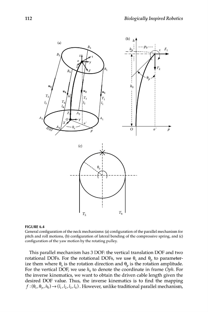
FIGURE 6.4
General configuration of the neck mechanisms: (a) configuration of the parallel mechanism for
pitch and roll motions, (b) configuration of lateral bending of the compressive spring, and (c)
configuration of the yaw motion by the rotating pulley.
This parallel mechanism has 3 DOF: the vertical translation DOF and two
rotational DOFs. For the rotational DOFs, we use θ s and θ p to parameterize them where θ s is the rotation direction and θ p is the rotation amplitude.
For the vertical DOF, we use h 0 to denote the coordinate in frame Oph. For
the inverse kinematics, we want to obtain the driven cable length given the
desired DOF value. Thus, the inverse kinematics is to find the mapping
f : ( s , p , h 0 ) → (l 1 , l 2 , l 3 , l 4
θ θ
) . However, unlike traditional parallel mechanism,
B 2
B 1
A 3
y
x
T 3
Y
X
O
Z
z
F
τ
l 3
A 1
A 2
B 3
u 3
B 4
A 4
T 4
h
l 4
u 4
T 2
T 1
l 2
l 1
u 2
u 1
o
o´
p
θ s
h
O
p
h 0
o´
F 1
F 2
τ
θ p
p b
h b
(b)
(c)
T 6
T 5
θ y
112
Biologically Inspired Robotics
FIGURE 6.4
General configuration of the neck mechanisms: (a) configuration of the parallel mechanism for
pitch and roll motions, (b) configuration of lateral bending of the compressive spring, and (c)
configuration of the yaw motion by the rotating pulley.
This parallel mechanism has 3 DOF: the vertical translation DOF and two
rotational DOFs. For the rotational DOFs, we use θ s and θ p to parameterize them where θ s is the rotation direction and θ p is the rotation amplitude.
For the vertical DOF, we use h 0 to denote the coordinate in frame Oph. For
the inverse kinematics, we want to obtain the driven cable length given the
desired DOF value. Thus, the inverse kinematics is to find the mapping
f : ( s , p , h 0 ) → (l 1 , l 2 , l 3 , l 4
θ θ
) . However, unlike traditional parallel mechanism,