

266
P. Sreeja and S. Singh
0.8
0.9
0.9
1.0
1.0
1.1
1.1
1.2
1.2
0
50 100 150 200 250 300 350 400 450 500 550 600 650 700 750 800 850 900 950 1000
Velocity (m/s)
Main Channel Distance (m)
Velocity For All The Three Cases
Without Bridge
Existing (Single) Bridge
Parallel Bridge
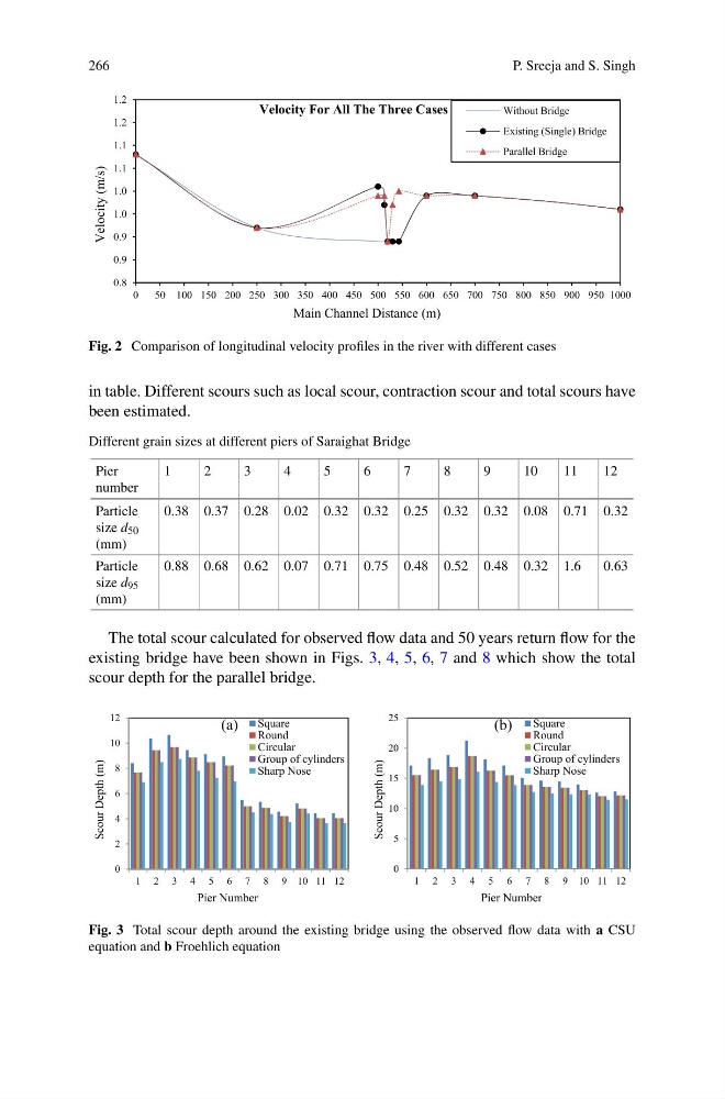
Fig. 2 Comparison of longitudinal velocity profiles in the river with different cases
in table. Different scours such as local scour, contraction scour and total scours have
been estimated.
Different grain sizes at different piers of Saraighat Bridge
Pier
number
1
2
3
4
5
6
7
8
9
10
11
12
Particle
size d 50
(mm)
0.38 0.37 0.28 0.02 0.32 0.32 0.25 0.32 0.32 0.08 0.71 0.32
Particle
size d 95
(mm)
0.88 0.68 0.62 0.07 0.71 0.75 0.48 0.52 0.48 0.32 1.6
0.63
The total scour calculated for observed flow data and 50 years return flow for the
existing bridge have been shown in Figs. 3, 4, 5, 6, 7 and 8 which show the total
scour depth for the parallel bridge.
0
2
4
6
8
10
12
1 2 3 4 5 6 7 8 9 10 11 12
Scour Depth (m)
Pier Number
(a) Square
Round
Circular
Group of cylinders
Sharp Nose
0
5
10
15
20
25
1 2 3 4 5 6 7 8 9 10 11 12
Scour Depth (m)
Pier Number
(b) Square
Round
Circular
Group of cylinders
Sharp Nose
Fig. 3 Total scour depth around the existing bridge using the observed flow data with a CSU
equation and b Froehlich equation
P. Sreeja and S. Singh
0.8
0.9
0.9
1.0
1.0
1.1
1.1
1.2
1.2
0
50 100 150 200 250 300 350 400 450 500 550 600 650 700 750 800 850 900 950 1000
Velocity (m/s)
Main Channel Distance (m)
Velocity For All The Three Cases
Without Bridge
Existing (Single) Bridge
Parallel Bridge
Fig. 2 Comparison of longitudinal velocity profiles in the river with different cases
in table. Different scours such as local scour, contraction scour and total scours have
been estimated.
Different grain sizes at different piers of Saraighat Bridge
Pier
number
1
2
3
4
5
6
7
8
9
10
11
12
Particle
size d 50
(mm)
0.38 0.37 0.28 0.02 0.32 0.32 0.25 0.32 0.32 0.08 0.71 0.32
Particle
size d 95
(mm)
0.88 0.68 0.62 0.07 0.71 0.75 0.48 0.52 0.48 0.32 1.6
0.63
The total scour calculated for observed flow data and 50 years return flow for the
existing bridge have been shown in Figs. 3, 4, 5, 6, 7 and 8 which show the total
scour depth for the parallel bridge.
0
2
4
6
8
10
12
1 2 3 4 5 6 7 8 9 10 11 12
Scour Depth (m)
Pier Number
(a) Square
Round
Circular
Group of cylinders
Sharp Nose
0
5
10
15
20
25
1 2 3 4 5 6 7 8 9 10 11 12
Scour Depth (m)
Pier Number
(b) Square
Round
Circular
Group of cylinders
Sharp Nose
Fig. 3 Total scour depth around the existing bridge using the observed flow data with a CSU
equation and b Froehlich equation