

52
A. Acharyya et al.
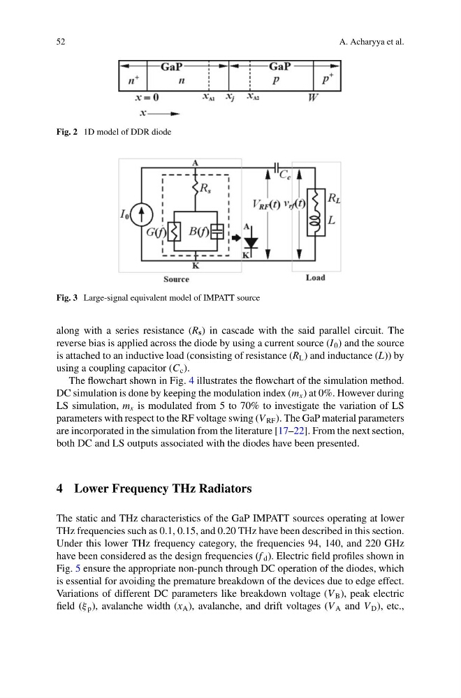
Fig. 2 1D model of DDR diode
Fig. 3 Large-signal equivalent model of IMPATT source
along with a series resistance (R s ) in cascade with the said parallel circuit. The
reverse bias is applied across the diode by using a current source (I 0 ) and the source
is attached to an inductive load (consisting of resistance (R L ) and inductance (L)) by
using a coupling capacitor (C c ).
The flowchart shown in Fig. 4 illustrates the flowchart of the simulation method.
DC simulation is done by keeping the modulation index (m x ) at 0%. However during
LS simulation, m x is modulated from 5 to 70% to investigate the variation of LS
parameters with respect to the RF voltage swing (V RF ). The GaP material parameters
are incorporated in the simulation from the literature [17–22]. From the next section,
both DC and LS outputs associated with the diodes have been presented.
4 Lower Frequency THz Radiators
The static and THz characteristics of the GaP IMPATT sources operating at lower
THz frequencies such as 0.1, 0.15, and 0.20 THz have been described in this section.
Under this lower THz frequency category, the frequencies 94, 140, and 220 GHz
have been considered as the design frequencies (f d ). Electric field profiles shown in
Fig. 5 ensure the appropriate non-punch through DC operation of the diodes, which
is essential for avoiding the premature breakdown of the devices due to edge effect.
Variations of different DC parameters like breakdown voltage (V B ), peak electric
field (ξ p ), avalanche width (x A ), avalanche, and drift voltages (V A and V D ), etc.,
A. Acharyya et al.
Fig. 2 1D model of DDR diode
Fig. 3 Large-signal equivalent model of IMPATT source
along with a series resistance (R s ) in cascade with the said parallel circuit. The
reverse bias is applied across the diode by using a current source (I 0 ) and the source
is attached to an inductive load (consisting of resistance (R L ) and inductance (L)) by
using a coupling capacitor (C c ).
The flowchart shown in Fig. 4 illustrates the flowchart of the simulation method.
DC simulation is done by keeping the modulation index (m x ) at 0%. However during
LS simulation, m x is modulated from 5 to 70% to investigate the variation of LS
parameters with respect to the RF voltage swing (V RF ). The GaP material parameters
are incorporated in the simulation from the literature [17–22]. From the next section,
both DC and LS outputs associated with the diodes have been presented.
4 Lower Frequency THz Radiators
The static and THz characteristics of the GaP IMPATT sources operating at lower
THz frequencies such as 0.1, 0.15, and 0.20 THz have been described in this section.
Under this lower THz frequency category, the frequencies 94, 140, and 220 GHz
have been considered as the design frequencies (f d ). Electric field profiles shown in
Fig. 5 ensure the appropriate non-punch through DC operation of the diodes, which
is essential for avoiding the premature breakdown of the devices due to edge effect.
Variations of different DC parameters like breakdown voltage (V B ), peak electric
field (ξ p ), avalanche width (x A ), avalanche, and drift voltages (V A and V D ), etc.,