

TOAD-Based Frequency-Encoded All Optical …
181
filter makes the output of the TOAD T 7 at frequency υ 2 and thus the final output is
at υ 2 , i.e., ‘HIGH’.
Case (4): When input A is at frequency υ 2 , the small portion of signals through
the υ 2 pass filter makes the control input of the TOAD T 2 is υ 2 . In this condition
the control signal of the TOAD T 2 forces the data signal of frequency υ 1 transmitted
through the port 1 of the TOAD T 2 and output of the TOAD T 2 is υ 1 . Similarly,
when input B is at frequency υ 2 , the small portion of signals through the υ 2 pass
filter makes the control input of the TOAD T 4 is υ 2 . In this condition, the control
signal of the TOAD T 4 forces the data signal of frequency υ 1 transmitted through
the port 1 of the TOAD T 4 and output of the TOAD T 4 is υ 1. So both the outputs of
TOAD T 2 and T 4 are signal frequency υ 1 and this signals passes through the υ 1 pass
filter makes the output of the TOAD T 5 is υ 1 and TOAD T 6 is υ 1 . In this situation,
there is no control signal receives of TOAD T 7 . As the control is absent, SOA gain
is unsaturated; hence, the data signal of frequency υ 1 comes out at the port 2 of the
TOAD T 7. This makes the final output at frequency υ 1 , i.e., ‘LOW’.
Therefore, from the above discussions, we found the output becomes signals at
frequencies υ 1 υ 2 υ 2 υ 1 which is the output of frequency-encoded XOR gate.
4 Frequency-Encoded AND Gate for Carry Generation
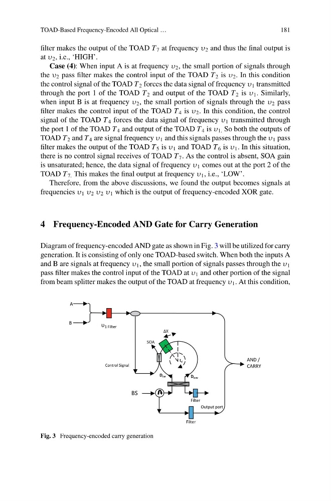
Diagram of frequency-encoded AND gate as shown in Fig. 3 will be utilized for carry
generation. It is consisting of only one TOAD-based switch. When both the inputs A
and B are signals at frequency υ 1 , the small portion of signals passes through the υ 1
pass filter makes the control input of the TOAD at υ 1 and other portion of the signal
from beam splitter makes the output of the TOAD at frequency υ 1 . At this condition,
AND /
CARRY
td
SOA
∆X
Dccw
Dcw
Filter
Filter
Output port
A
B
υ 1 Filter
BS
Control Signal
Fig. 3 Frequency-encoded carry generation
181
filter makes the output of the TOAD T 7 at frequency υ 2 and thus the final output is
at υ 2 , i.e., ‘HIGH’.
Case (4): When input A is at frequency υ 2 , the small portion of signals through
the υ 2 pass filter makes the control input of the TOAD T 2 is υ 2 . In this condition
the control signal of the TOAD T 2 forces the data signal of frequency υ 1 transmitted
through the port 1 of the TOAD T 2 and output of the TOAD T 2 is υ 1 . Similarly,
when input B is at frequency υ 2 , the small portion of signals through the υ 2 pass
filter makes the control input of the TOAD T 4 is υ 2 . In this condition, the control
signal of the TOAD T 4 forces the data signal of frequency υ 1 transmitted through
the port 1 of the TOAD T 4 and output of the TOAD T 4 is υ 1. So both the outputs of
TOAD T 2 and T 4 are signal frequency υ 1 and this signals passes through the υ 1 pass
filter makes the output of the TOAD T 5 is υ 1 and TOAD T 6 is υ 1 . In this situation,
there is no control signal receives of TOAD T 7 . As the control is absent, SOA gain
is unsaturated; hence, the data signal of frequency υ 1 comes out at the port 2 of the
TOAD T 7. This makes the final output at frequency υ 1 , i.e., ‘LOW’.
Therefore, from the above discussions, we found the output becomes signals at
frequencies υ 1 υ 2 υ 2 υ 1 which is the output of frequency-encoded XOR gate.
4 Frequency-Encoded AND Gate for Carry Generation
Diagram of frequency-encoded AND gate as shown in Fig. 3 will be utilized for carry
generation. It is consisting of only one TOAD-based switch. When both the inputs A
and B are signals at frequency υ 1 , the small portion of signals passes through the υ 1
pass filter makes the control input of the TOAD at υ 1 and other portion of the signal
from beam splitter makes the output of the TOAD at frequency υ 1 . At this condition,
AND /
CARRY
td
SOA
∆X
Dccw
Dcw
Filter
Filter
Output port
A
B
υ 1 Filter
BS
Control Signal
Fig. 3 Frequency-encoded carry generation