

19 Magnetoelectric Near Fields
541
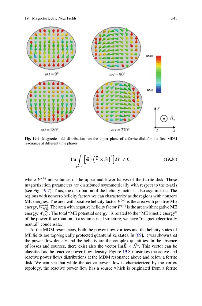
Fig. 19.4 Magnetic field distributions on the upper plane of a ferrite disk for the first MDM
resonance at different time phases
Im
V (±)
m ·
∇ × ×
m
∗
dV = 0,
(19.36)
where V
(±) are volumes of the upper and lower halves of the ferrite disk. These
magnetization parameters are distributed asymmetrically with respect to the z-axis
(see Fig. 19.7). Thus, the distribution of the helicity factor is also asymmetric. The
regions with nonzero helicity factors we can characterize as the regions with nonzero
ME energies. The area with positive helicity factor F
(+) is the area with positive ME
energy, W
(+)
M E . The area with negative helicity factor F
(−) is the area with negative ME
energy, W
(−)
M E . The total “ME potential energy” is related to the “ME kinetic energy”
of the power-flow rotation. It a symmetrical structure, we have “magnetoelectrically
neutral” condensate.
At the MDM resonances, both the power-flow vortices and the helicity states of
ME fields are topologically protected quantumlike states. In [69], it was shown that
the power-flow density and the helicity are the complex quantities. In the absence
of losses and sources, there exist also the vector Im
E ×
H
∗ . This vector can be
classified as the reactive power flow density. Figure 19.8 illustrates the active and
reactive power flows distributions at the MDM resonance above and below a ferrite
disk. We can see that while the active power flow is characterized by the vortex
topology, the reactive power flow has a source which is originated from a ferrite
541
Fig. 19.4 Magnetic field distributions on the upper plane of a ferrite disk for the first MDM
resonance at different time phases
Im
V (±)
m ·
∇ × ×
m
∗
dV = 0,
(19.36)
where V
(±) are volumes of the upper and lower halves of the ferrite disk. These
magnetization parameters are distributed asymmetrically with respect to the z-axis
(see Fig. 19.7). Thus, the distribution of the helicity factor is also asymmetric. The
regions with nonzero helicity factors we can characterize as the regions with nonzero
ME energies. The area with positive helicity factor F
(+) is the area with positive ME
energy, W
(+)
M E . The area with negative helicity factor F
(−) is the area with negative ME
energy, W
(−)
M E . The total “ME potential energy” is related to the “ME kinetic energy”
of the power-flow rotation. It a symmetrical structure, we have “magnetoelectrically
neutral” condensate.
At the MDM resonances, both the power-flow vortices and the helicity states of
ME fields are topologically protected quantumlike states. In [69], it was shown that
the power-flow density and the helicity are the complex quantities. In the absence
of losses and sources, there exist also the vector Im
E ×
H
∗ . This vector can be
classified as the reactive power flow density. Figure 19.8 illustrates the active and
reactive power flows distributions at the MDM resonance above and below a ferrite
disk. We can see that while the active power flow is characterized by the vortex
topology, the reactive power flow has a source which is originated from a ferrite