

500
A. Karabchevsky et al.
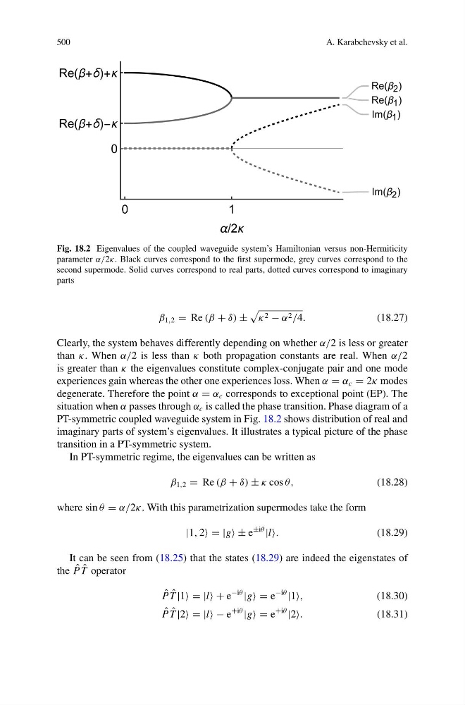
Fig. 18.2 Eigenvalues of the coupled waveguide system’s Hamiltonian versus non-Hermiticity
parameter α/2κ. Black curves correspond to the first supermode, grey curves correspond to the
second supermode. Solid curves correspond to real parts, dotted curves correspond to imaginary
parts
β 1,2 = Re (β + δ) ±
κ 2 − α 2 /4.
(18.27)
Clearly, the system behaves differently depending on whether α/2 is less or greater
than κ. When α/2 is less than κ both propagation constants are real. When α/2
is greater than κ the eigenvalues constitute complex-conjugate pair and one mode
experiences gain whereas the other one experiences loss. When α = α c = 2κ modes
degenerate. Therefore the point α = α c corresponds to exceptional point (EP). The
situation when α passes through α c is called the phase transition. Phase diagram of a
PT-symmetric coupled waveguide system in Fig. 18.2 shows distribution of real and
imaginary parts of system’s eigenvalues. It illustrates a typical picture of the phase
transition in a PT-symmetric system.
In PT-symmetric regime, the eigenvalues can be written as
β 1,2 = Re (β + δ) ± κ cos θ,
(18.28)
where sin θ = α/2κ. With this parametrization supermodes take the form
|1, 2 = |g ± e
±iθ
|l
(18.29)
It can be seen from (18.25) that the states (18.29) are indeed the eigenstates of
the ˆ
P ˆ
T operator
ˆ
P ˆ
T |1 = |l + e
−iθ
|g = e
−iθ
|1
(18.30)
ˆ
P ˆ
T |2 = |l − e
+iθ
|g = e
+iθ
|2
(18.31)
A. Karabchevsky et al.
Fig. 18.2 Eigenvalues of the coupled waveguide system’s Hamiltonian versus non-Hermiticity
parameter α/2κ. Black curves correspond to the first supermode, grey curves correspond to the
second supermode. Solid curves correspond to real parts, dotted curves correspond to imaginary
parts
β 1,2 = Re (β + δ) ±
κ 2 − α 2 /4.
(18.27)
Clearly, the system behaves differently depending on whether α/2 is less or greater
than κ. When α/2 is less than κ both propagation constants are real. When α/2
is greater than κ the eigenvalues constitute complex-conjugate pair and one mode
experiences gain whereas the other one experiences loss. When α = α c = 2κ modes
degenerate. Therefore the point α = α c corresponds to exceptional point (EP). The
situation when α passes through α c is called the phase transition. Phase diagram of a
PT-symmetric coupled waveguide system in Fig. 18.2 shows distribution of real and
imaginary parts of system’s eigenvalues. It illustrates a typical picture of the phase
transition in a PT-symmetric system.
In PT-symmetric regime, the eigenvalues can be written as
β 1,2 = Re (β + δ) ± κ cos θ,
(18.28)
where sin θ = α/2κ. With this parametrization supermodes take the form
|1, 2 = |g ± e
±iθ
|l
(18.29)
It can be seen from (18.25) that the states (18.29) are indeed the eigenstates of
the ˆ
P ˆ
T operator
ˆ
P ˆ
T |1 = |l + e
−iθ
|g = e
−iθ
|1
(18.30)
ˆ
P ˆ
T |2 = |l − e
+iθ
|g = e
+iθ
|2
(18.31)