

474
A. Martín-Ruiz et al.
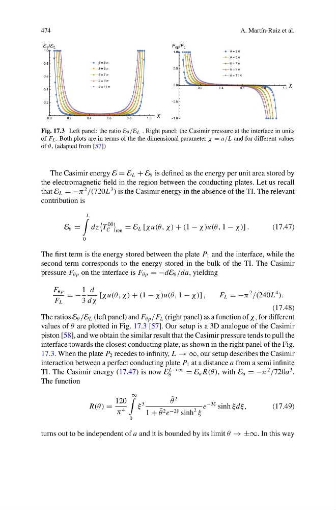
Fig. 17.3 Left panel: the ratio E θ /E L . Right panel: the Casimir pressure at the interface in units
of F L . Both plots are in terms of the the dimensional parameter χ = a/L and for different values
of θ, (adapted from [57])
The Casimir energy E = E L + E θ is defined as the energy per unit area stored by
the electromagnetic field in the region between the conducting plates. Let us recall
that E L = −π
2
/(720L
3
) is the Casimir energy in the absence of the TI. The relevant
contribution is
E θ =
L
0
dz
T
00
C
ren
= E L [χ u(θ, χ ) + (1 − χ)u(θ, 1 − χ)] .
(17.47)
The first term is the energy stored between the plate P 1 and the interface, while the
second term corresponds to the energy stored in the bulk of the TI. The Casimir
pressure F θ p on the interface is F θ p = −dE θ /da, yielding
F θ p
F L
= −
1
3
d
dχ
[χ u(θ, χ ) + (1 − χ)u(θ, 1 − χ)] ,
F L = −π
2
/(240L
4
).
(17.48)
The ratios E θ /E L (left panel) and F θ p /F L (right panel) as a function of χ , for different
values of θ are plotted in Fig. 17.3 [57]. Our setup is a 3D analogue of the Casimir
piston [58], and we obtain the similar result that the Casimir pressure tends to pull the
interface towards the closest conducting plate, as shown in the right panel of the Fig.
17.3. When the plate P 2 recedes to infinity, L → ∞, our setup describes the Casimir
interaction between a perfect conducting plate P 1 at a distance a from a semi infinite
TI. The Casimir energy (17.47) is now E
L→∞
θ
= E a R(θ ), with E a = −π
2
/720a
3 .
The function
R(θ ) =
120
π 4
∞
0
ξ
3
˜
θ
2
1 + ˜
θ 2 e −2ξ sinh
2
ξ
e
−3ξ sinh ξ dξ,
(17.49)
turns out to be independent of a and it is bounded by its limit θ → ±∞. In this way
A. Martín-Ruiz et al.
Fig. 17.3 Left panel: the ratio E θ /E L . Right panel: the Casimir pressure at the interface in units
of F L . Both plots are in terms of the the dimensional parameter χ = a/L and for different values
of θ, (adapted from [57])
The Casimir energy E = E L + E θ is defined as the energy per unit area stored by
the electromagnetic field in the region between the conducting plates. Let us recall
that E L = −π
2
/(720L
3
) is the Casimir energy in the absence of the TI. The relevant
contribution is
E θ =
L
0
dz
T
00
C
ren
= E L [χ u(θ, χ ) + (1 − χ)u(θ, 1 − χ)] .
(17.47)
The first term is the energy stored between the plate P 1 and the interface, while the
second term corresponds to the energy stored in the bulk of the TI. The Casimir
pressure F θ p on the interface is F θ p = −dE θ /da, yielding
F θ p
F L
= −
1
3
d
dχ
[χ u(θ, χ ) + (1 − χ)u(θ, 1 − χ)] ,
F L = −π
2
/(240L
4
).
(17.48)
The ratios E θ /E L (left panel) and F θ p /F L (right panel) as a function of χ , for different
values of θ are plotted in Fig. 17.3 [57]. Our setup is a 3D analogue of the Casimir
piston [58], and we obtain the similar result that the Casimir pressure tends to pull the
interface towards the closest conducting plate, as shown in the right panel of the Fig.
17.3. When the plate P 2 recedes to infinity, L → ∞, our setup describes the Casimir
interaction between a perfect conducting plate P 1 at a distance a from a semi infinite
TI. The Casimir energy (17.47) is now E
L→∞
θ
= E a R(θ ), with E a = −π
2
/720a
3 .
The function
R(θ ) =
120
π 4
∞
0
ξ
3
˜
θ
2
1 + ˜
θ 2 e −2ξ sinh
2
ξ
e
−3ξ sinh ξ dξ,
(17.49)
turns out to be independent of a and it is bounded by its limit θ → ±∞. In this way