

14 Topology in Magnetism
387
0
(b)
10
4
10
0
10
-3
10
4
10
0
10
-3
1.4
1.2
1.0
(a)
0.2
0.5
0.8
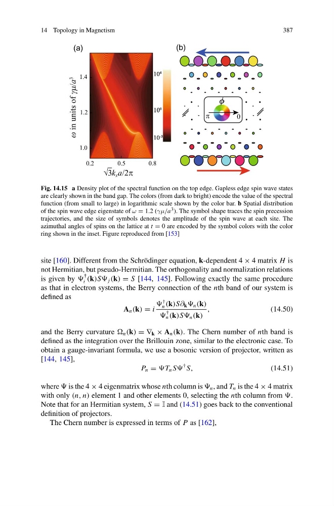
Fig. 14.15 a Density plot of the spectral function on the top edge. Gapless edge spin wave states
are clearly shown in the band gap. The colors (from dark to bright) encode the value of the spectral
function (from small to large) in logarithmic scale shown by the color bar. b Spatial distribution
of the spin wave edge eigenstate of ω = 1.2 (γμ/a 3 ). The symbol shape traces the spin precession
trajectories, and the size of symbols denotes the amplitude of the spin wave at each site. The
azimuthal angles of spins on the lattice at t = 0 are encoded by the symbol colors with the color
ring shown in the inset. Figure reproduced from [153]
site [160]. Different from the Schrödinger equation, k-dependent 4 × 4 matrix H is
not Hermitian, but pseudo-Hermitian. The orthogonality and normalization relations
is given by
†
i (k)S j (k) = S [144, 145]. Following exactly the same procedure
as that in electron systems, the Berry connection of the nth band of our system is
defined as
A n (k) = i
†
n (k)S∂ k n (k)
†
n (k)S n (k)
,
(14.50)
and the Berry curvature n (k) = ∇ k × A n (k). The Chern number of nth band is
defined as the integration over the Brillouin zone, similar to the electronic case. To
obtain a gauge-invariant formula, we use a bosonic version of projector, written as
[144, 145],
P n = n S
† S,
(14.51)
where is the 4 × 4 eigenmatrix whose nth column is n , and T n is the 4 × 4 matrix
with only (n, n) element 1 and other elements 0, selecting the nth column from
Note that for an Hermitian system, S = I and (14.51) goes back to the conventional
definition of projectors.
The Chern number is expressed in terms of P as [162],
387
0
(b)
10
4
10
0
10
-3
10
4
10
0
10
-3
1.4
1.2
1.0
(a)
0.2
0.5
0.8
Fig. 14.15 a Density plot of the spectral function on the top edge. Gapless edge spin wave states
are clearly shown in the band gap. The colors (from dark to bright) encode the value of the spectral
function (from small to large) in logarithmic scale shown by the color bar. b Spatial distribution
of the spin wave edge eigenstate of ω = 1.2 (γμ/a 3 ). The symbol shape traces the spin precession
trajectories, and the size of symbols denotes the amplitude of the spin wave at each site. The
azimuthal angles of spins on the lattice at t = 0 are encoded by the symbol colors with the color
ring shown in the inset. Figure reproduced from [153]
site [160]. Different from the Schrödinger equation, k-dependent 4 × 4 matrix H is
not Hermitian, but pseudo-Hermitian. The orthogonality and normalization relations
is given by
†
i (k)S j (k) = S [144, 145]. Following exactly the same procedure
as that in electron systems, the Berry connection of the nth band of our system is
defined as
A n (k) = i
†
n (k)S∂ k n (k)
†
n (k)S n (k)
,
(14.50)
and the Berry curvature n (k) = ∇ k × A n (k). The Chern number of nth band is
defined as the integration over the Brillouin zone, similar to the electronic case. To
obtain a gauge-invariant formula, we use a bosonic version of projector, written as
[144, 145],
P n = n S
† S,
(14.51)
where is the 4 × 4 eigenmatrix whose nth column is n , and T n is the 4 × 4 matrix
with only (n, n) element 1 and other elements 0, selecting the nth column from
Note that for an Hermitian system, S = I and (14.51) goes back to the conventional
definition of projectors.
The Chern number is expressed in terms of P as [162],