

14 Topology in Magnetism
367
(a)
(b)
(c)
(d)
(e)
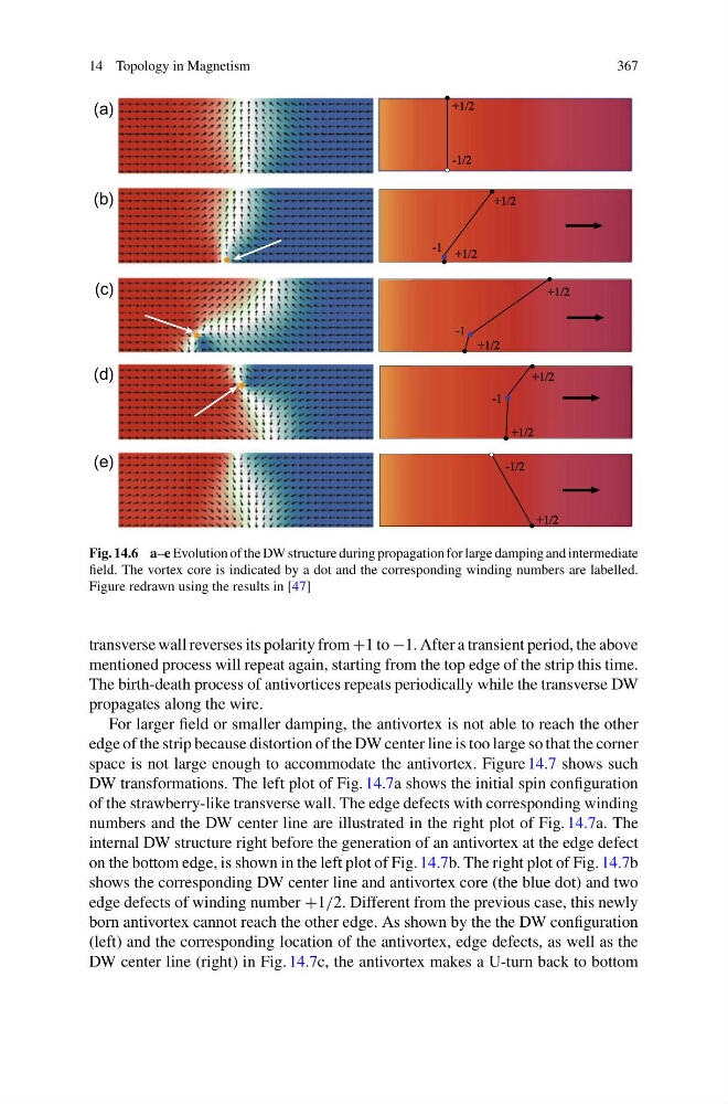
Fig. 14.6 a–e Evolution of the DW structure during propagation for large damping and intermediate
field. The vortex core is indicated by a dot and the corresponding winding numbers are labelled.
Figure redrawn using the results in [47]
transverse wall reverses its polarity from +1 to −1. After a transient period, the above
mentioned process will repeat again, starting from the top edge of the strip this time.
The birth-death process of antivortices repeats periodically while the transverse DW
propagates along the wire.
For larger field or smaller damping, the antivortex is not able to reach the other
edge of the strip because distortion of the DW center line is too large so that the corner
space is not large enough to accommodate the antivortex. Figure 14.7 shows such
DW transformations. The left plot of Fig. 14.7a shows the initial spin configuration
of the strawberry-like transverse wall. The edge defects with corresponding winding
numbers and the DW center line are illustrated in the right plot of Fig. 14.7a. The
internal DW structure right before the generation of an antivortex at the edge defect
on the bottom edge, is shown in the left plot of Fig. 14.7b. The right plot of Fig. 14.7b
shows the corresponding DW center line and antivortex core (the blue dot) and two
edge defects of winding number +1/2. Different from the previous case, this newly
born antivortex cannot reach the other edge. As shown by the the DW configuration
(left) and the corresponding location of the antivortex, edge defects, as well as the
DW center line (right) in Fig. 14.7c, the antivortex makes a U-turn back to bottom
367
(a)
(b)
(c)
(d)
(e)
Fig. 14.6 a–e Evolution of the DW structure during propagation for large damping and intermediate
field. The vortex core is indicated by a dot and the corresponding winding numbers are labelled.
Figure redrawn using the results in [47]
transverse wall reverses its polarity from +1 to −1. After a transient period, the above
mentioned process will repeat again, starting from the top edge of the strip this time.
The birth-death process of antivortices repeats periodically while the transverse DW
propagates along the wire.
For larger field or smaller damping, the antivortex is not able to reach the other
edge of the strip because distortion of the DW center line is too large so that the corner
space is not large enough to accommodate the antivortex. Figure 14.7 shows such
DW transformations. The left plot of Fig. 14.7a shows the initial spin configuration
of the strawberry-like transverse wall. The edge defects with corresponding winding
numbers and the DW center line are illustrated in the right plot of Fig. 14.7a. The
internal DW structure right before the generation of an antivortex at the edge defect
on the bottom edge, is shown in the left plot of Fig. 14.7b. The right plot of Fig. 14.7b
shows the corresponding DW center line and antivortex core (the blue dot) and two
edge defects of winding number +1/2. Different from the previous case, this newly
born antivortex cannot reach the other edge. As shown by the the DW configuration
(left) and the corresponding location of the antivortex, edge defects, as well as the
DW center line (right) in Fig. 14.7c, the antivortex makes a U-turn back to bottom