

366
X. S. Wang and X. R. Wang
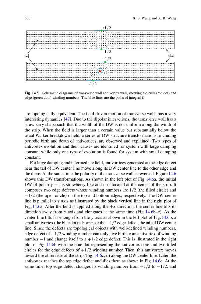
Fig. 14.5 Schematic diagrams of transverse wall and vortex wall, showing the bulk (red dot) and
edge (green dots) winding numbers. The blue lines are the paths of integral C
are topologically equivalent. The field-driven motion of transverse walls has a very
interesting dynamics [47]. Due to the dipolar interactions, the transverse wall has a
strawberry shape such that the width of the DW is not uniform along the width of
the strip. When the field is larger than a certain value but substantially below the
usual Walker breakdown field, a series of DW structure transformations, including
periodic birth and death of antivortices, are observed and explained. Two types of
antivortex evolution and their causes are identified for system with large damping
constant while only one type of evolution is found for system with small damping
constant.
For large damping and intermediate field, antivortices generated at the edge defect
near the tail of DW center line move along its DW center line to the other edge and
die there. At the same time the polarity of the transverse wall is reversed. Figure 14.6
shows this DW transformations. As shown in the left plot of Fig. 14.6a, the initial
DW of polarity +1 is strawberry-like and it is located at the center of the strip. It
composes two edge defects whose winding numbers are 1/2 (the filled circle) and
−1/2 (the open circle) on the top and bottom edges, respectively. The DW center
line is parallel to y axis as illustrated by the black vertical line in the right plot of
Fig. 14.6a. After the field is applied along the +x-direction, the center line tilts its
direction away from y axis and elongates at the same time (Fig. 14.6b–e). As the
center line tilts far enough from the y axis as shown in the left plot of Fig. 14.6b, a
small antivortex (the blue dot) is born near the −1/2 edge defect, the tail of DW center
line. Since the defects are topological objects with well-defined winding numbers,
edge defect of −1/2 winding number can only give birth to an antivortex of winding
number −1 and change itself to a +1/2 edge defect. This is illustrated in the right
plot of Fig. 14.6b with the blue dot representing the antivortex core and two filled
circles for the edge defects of +1/2 winding number. Then, this antivortex moves
toward the other side of the strip (Fig. 14.6c, d) along the DW center line. Later, the
antivortex reaches the top edge defect and dies there as shown in Fig. 14.6e. At the
same time, top edge defect changes its winding number from +1/2 to −1/2, and
X. S. Wang and X. R. Wang
Fig. 14.5 Schematic diagrams of transverse wall and vortex wall, showing the bulk (red dot) and
edge (green dots) winding numbers. The blue lines are the paths of integral C
are topologically equivalent. The field-driven motion of transverse walls has a very
interesting dynamics [47]. Due to the dipolar interactions, the transverse wall has a
strawberry shape such that the width of the DW is not uniform along the width of
the strip. When the field is larger than a certain value but substantially below the
usual Walker breakdown field, a series of DW structure transformations, including
periodic birth and death of antivortices, are observed and explained. Two types of
antivortex evolution and their causes are identified for system with large damping
constant while only one type of evolution is found for system with small damping
constant.
For large damping and intermediate field, antivortices generated at the edge defect
near the tail of DW center line move along its DW center line to the other edge and
die there. At the same time the polarity of the transverse wall is reversed. Figure 14.6
shows this DW transformations. As shown in the left plot of Fig. 14.6a, the initial
DW of polarity +1 is strawberry-like and it is located at the center of the strip. It
composes two edge defects whose winding numbers are 1/2 (the filled circle) and
−1/2 (the open circle) on the top and bottom edges, respectively. The DW center
line is parallel to y axis as illustrated by the black vertical line in the right plot of
Fig. 14.6a. After the field is applied along the +x-direction, the center line tilts its
direction away from y axis and elongates at the same time (Fig. 14.6b–e). As the
center line tilts far enough from the y axis as shown in the left plot of Fig. 14.6b, a
small antivortex (the blue dot) is born near the −1/2 edge defect, the tail of DW center
line. Since the defects are topological objects with well-defined winding numbers,
edge defect of −1/2 winding number can only give birth to an antivortex of winding
number −1 and change itself to a +1/2 edge defect. This is illustrated in the right
plot of Fig. 14.6b with the blue dot representing the antivortex core and two filled
circles for the edge defects of +1/2 winding number. Then, this antivortex moves
toward the other side of the strip (Fig. 14.6c, d) along the DW center line. Later, the
antivortex reaches the top edge defect and dies there as shown in Fig. 14.6e. At the
same time, top edge defect changes its winding number from +1/2 to −1/2, and