

198
M. Mochizuki
R (t)
AC
m(r)
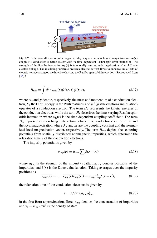
Fig. 8.7 Schematic illustration of a magnetic bilayer system in which local magnetizations m(r)
couple to a conduction-electron system with the time-dependent Rashba spin-orbit interaction. The
strength of the Rashba interaction α R (t) is temporally varying under application of an AC gate
electric voltage. The insulating substrate prevents electric-current flows to enhance the effects of
electric voltage acting on the interface hosting the Rashba spin-orbit interaction (Reproduced from
[35].)
H imp =
d
2 r v imp (r)ψ
†
(r, t)ψ(r, t),
(8.17)
where m e and p denote, respectively, the mass and momentum of a conduction electron, E F the Fermi energy, σ the Pauli matrices, and ψ
† (ψ) the creation (annihilation)
operator of a conduction electron. The term H K represents the kinetic energies of
the conduction electrons, while the term H R describes the time-varying Rashba spinorbit interaction where α R (t) is the time-dependent coupling coefficient. The term
H ex represents the exchange interaction between the conduction-electron spins and
the local magnetization where J ex and m are the coupling constant and the normalized local magnetization vector, respectively. The term H imp depicts the scattering
potentials from spatially distributed nonmagnetic impurities, which determine the
relaxation time τ of the conduction electrons.
The impurity potential is given by,
v imp (r) = u imp
i
δ(r − r i )
(8.18)
where u imp is the strength of the impurity scattering, r i denotes positions of the
impurities, and δ(r) is the Dirac delta function. Taking averages over the impurity
positions as
v imp (r) = 0, v imp (r)v imp (r ) = n imp u
2
imp δ(r − r
),
(8.19)
the relaxation time of the conduction electrons is given by
τ = e n imp u
2
imp
(8.20)
in the first Born approximation. Here, n imp denotes the concentration of impurities
and ν e = m e /2π
2 is the density of state.
M. Mochizuki
R (t)
AC
m(r)
Fig. 8.7 Schematic illustration of a magnetic bilayer system in which local magnetizations m(r)
couple to a conduction-electron system with the time-dependent Rashba spin-orbit interaction. The
strength of the Rashba interaction α R (t) is temporally varying under application of an AC gate
electric voltage. The insulating substrate prevents electric-current flows to enhance the effects of
electric voltage acting on the interface hosting the Rashba spin-orbit interaction (Reproduced from
[35].)
H imp =
d
2 r v imp (r)ψ
†
(r, t)ψ(r, t),
(8.17)
where m e and p denote, respectively, the mass and momentum of a conduction electron, E F the Fermi energy, σ the Pauli matrices, and ψ
† (ψ) the creation (annihilation)
operator of a conduction electron. The term H K represents the kinetic energies of
the conduction electrons, while the term H R describes the time-varying Rashba spinorbit interaction where α R (t) is the time-dependent coupling coefficient. The term
H ex represents the exchange interaction between the conduction-electron spins and
the local magnetization where J ex and m are the coupling constant and the normalized local magnetization vector, respectively. The term H imp depicts the scattering
potentials from spatially distributed nonmagnetic impurities, which determine the
relaxation time τ of the conduction electrons.
The impurity potential is given by,
v imp (r) = u imp
i
δ(r − r i )
(8.18)
where u imp is the strength of the impurity scattering, r i denotes positions of the
impurities, and δ(r) is the Dirac delta function. Taking averages over the impurity
positions as
v imp (r) = 0, v imp (r)v imp (r ) = n imp u
2
imp δ(r − r
),
(8.19)
the relaxation time of the conduction electrons is given by
τ = e n imp u
2
imp
(8.20)
in the first Born approximation. Here, n imp denotes the concentration of impurities
and ν e = m e /2π
2 is the density of state.