

5 Light–Nanomatter Chiral Interaction in Optical-Force Effects
109
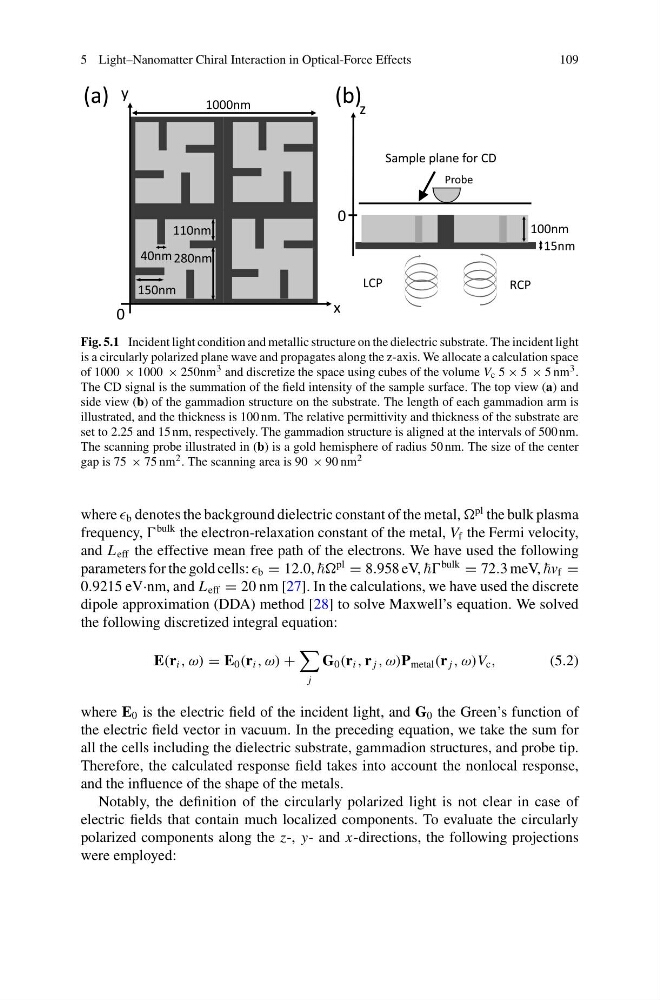
Fig. 5.1 Incident light condition and metallic structure on the dielectric substrate. The incident light
is a circularly polarized plane wave and propagates along the z-axis. We allocate a calculation space
of 1000 × 1000 × 250nm 3 and discretize the space using cubes of the volume V c 5 × 5 × 5 nm 3 .
The CD signal is the summation of the field intensity of the sample surface. The top view (a) and
side view (b) of the gammadion structure on the substrate. The length of each gammadion arm is
illustrated, and the thickness is 100 nm. The relative permittivity and thickness of the substrate are
set to 2.25 and 15 nm, respectively. The gammadion structure is aligned at the intervals of 500 nm.
The scanning probe illustrated in (b) is a gold hemisphere of radius 50 nm. The size of the center
gap is 75 × 75 nm 2 . The scanning area is 90 × 90 nm 2
where b denotes the background dielectric constant of the metal,
pl the bulk plasma
frequency,
bulk the electron-relaxation constant of the metal, V f the Fermi velocity,
and L eff the effective mean free path of the electrons. We have used the following
parameters for the gold cells: b = 12.0,
pl
= 8.958 eV,
bulk
= 72.3 meV, f =
0.9215 eV·nm, and L eff = 20 nm [27]. In the calculations, we have used the discrete
dipole approximation (DDA) method [28] to solve Maxwell’s equation. We solved
the following discretized integral equation:
E(r i , ω) = E 0 (r i , ω) +
j
G 0 (r i , r j , ω)P metal (r j , ω)V c ,
(5.2)
where E 0 is the electric field of the incident light, and G 0 the Green’s function of
the electric field vector in vacuum. In the preceding equation, we take the sum for
all the cells including the dielectric substrate, gammadion structures, and probe tip.
Therefore, the calculated response field takes into account the nonlocal response,
and the influence of the shape of the metals.
Notably, the definition of the circularly polarized light is not clear in case of
electric fields that contain much localized components. To evaluate the circularly
polarized components along the z-, y- and x-directions, the following projections
were employed:
109
Fig. 5.1 Incident light condition and metallic structure on the dielectric substrate. The incident light
is a circularly polarized plane wave and propagates along the z-axis. We allocate a calculation space
of 1000 × 1000 × 250nm 3 and discretize the space using cubes of the volume V c 5 × 5 × 5 nm 3 .
The CD signal is the summation of the field intensity of the sample surface. The top view (a) and
side view (b) of the gammadion structure on the substrate. The length of each gammadion arm is
illustrated, and the thickness is 100 nm. The relative permittivity and thickness of the substrate are
set to 2.25 and 15 nm, respectively. The gammadion structure is aligned at the intervals of 500 nm.
The scanning probe illustrated in (b) is a gold hemisphere of radius 50 nm. The size of the center
gap is 75 × 75 nm 2 . The scanning area is 90 × 90 nm 2
where b denotes the background dielectric constant of the metal,
pl the bulk plasma
frequency,
bulk the electron-relaxation constant of the metal, V f the Fermi velocity,
and L eff the effective mean free path of the electrons. We have used the following
parameters for the gold cells: b = 12.0,
pl
= 8.958 eV,
bulk
= 72.3 meV, f =
0.9215 eV·nm, and L eff = 20 nm [27]. In the calculations, we have used the discrete
dipole approximation (DDA) method [28] to solve Maxwell’s equation. We solved
the following discretized integral equation:
E(r i , ω) = E 0 (r i , ω) +
j
G 0 (r i , r j , ω)P metal (r j , ω)V c ,
(5.2)
where E 0 is the electric field of the incident light, and G 0 the Green’s function of
the electric field vector in vacuum. In the preceding equation, we take the sum for
all the cells including the dielectric substrate, gammadion structures, and probe tip.
Therefore, the calculated response field takes into account the nonlocal response,
and the influence of the shape of the metals.
Notably, the definition of the circularly polarized light is not clear in case of
electric fields that contain much localized components. To evaluate the circularly
polarized components along the z-, y- and x-directions, the following projections
were employed: