

60
A. V. Demareva et al.
β = max
min
1 − v min
1 − v f
, 1
, 0
,
(4.6)
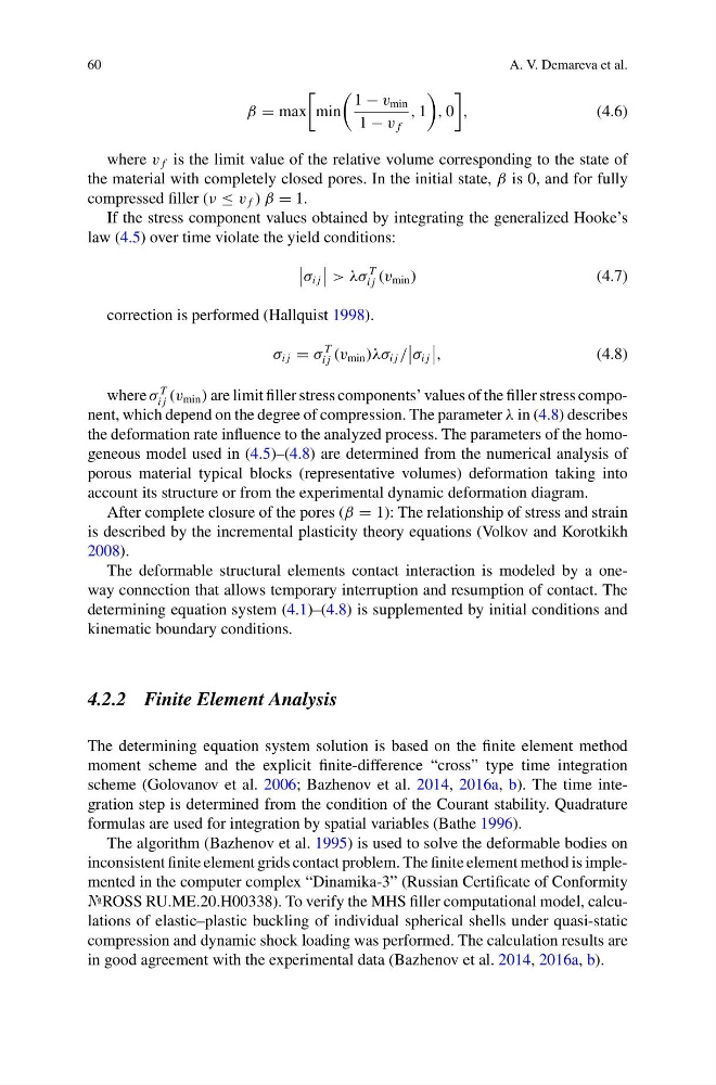
where v f is the limit value of the relative volume corresponding to the state of
the material with completely closed pores. In the initial state, β is 0, and for fully
compressed filler (ν ≤ v f ) β = 1.
If the stress component values obtained by integrating the generalized Hooke’s
law (4.5) over time violate the yield conditions:
σ i j
> λσ
T
i j (v min )
(4.7)
correction is performed (Hallquist 1998).
σ i j = σ
T
i j (v min )λσ i j /
σ i j
,
(4.8)
where σ
T
i j (v min ) are limit filler stress components’ values of the filler stress component, which depend on the degree of compression. The parameter λ in (4.8) describes
the deformation rate influence to the analyzed process. The parameters of the homogeneous model used in (4.5)–(4.8) are determined from the numerical analysis of
porous material typical blocks (representative volumes) deformation taking into
account its structure or from the experimental dynamic deformation diagram.
After complete closure of the pores (β = 1): The relationship of stress and strain
is described by the incremental plasticity theory equations (Volkov and Korotkikh
2008).
The deformable structural elements contact interaction is modeled by a oneway connection that allows temporary interruption and resumption of contact. The
determining equation system (4.1)–(4.8) is supplemented by initial conditions and
kinematic boundary conditions.
4.2.2 Finite Element Analysis
The determining equation system solution is based on the finite element method
moment scheme and the explicit finite-difference “cross” type time integration
scheme (Golovanov et al. 2006; Bazhenov et al. 2014, 2016a, b). The time integration step is determined from the condition of the Courant stability. Quadrature
formulas are used for integration by spatial variables (Bathe 1996).
The algorithm (Bazhenov et al. 1995) is used to solve the deformable bodies on
inconsistent finite element grids contact problem. The finite element method is implemented in the computer complex “Dinamika-3” (Russian Certificate of Conformity
№ROSS RU.ME.20.H00338). To verify the MHS filler computational model, calculations of elastic–plastic buckling of individual spherical shells under quasi-static
compression and dynamic shock loading was performed. The calculation results are
in good agreement with the experimental data (Bazhenov et al. 2014, 2016a, b).
A. V. Demareva et al.
β = max
min
1 − v min
1 − v f
, 1
, 0
,
(4.6)
where v f is the limit value of the relative volume corresponding to the state of
the material with completely closed pores. In the initial state, β is 0, and for fully
compressed filler (ν ≤ v f ) β = 1.
If the stress component values obtained by integrating the generalized Hooke’s
law (4.5) over time violate the yield conditions:
σ i j
> λσ
T
i j (v min )
(4.7)
correction is performed (Hallquist 1998).
σ i j = σ
T
i j (v min )λσ i j /
σ i j
,
(4.8)
where σ
T
i j (v min ) are limit filler stress components’ values of the filler stress component, which depend on the degree of compression. The parameter λ in (4.8) describes
the deformation rate influence to the analyzed process. The parameters of the homogeneous model used in (4.5)–(4.8) are determined from the numerical analysis of
porous material typical blocks (representative volumes) deformation taking into
account its structure or from the experimental dynamic deformation diagram.
After complete closure of the pores (β = 1): The relationship of stress and strain
is described by the incremental plasticity theory equations (Volkov and Korotkikh
2008).
The deformable structural elements contact interaction is modeled by a oneway connection that allows temporary interruption and resumption of contact. The
determining equation system (4.1)–(4.8) is supplemented by initial conditions and
kinematic boundary conditions.
4.2.2 Finite Element Analysis
The determining equation system solution is based on the finite element method
moment scheme and the explicit finite-difference “cross” type time integration
scheme (Golovanov et al. 2006; Bazhenov et al. 2014, 2016a, b). The time integration step is determined from the condition of the Courant stability. Quadrature
formulas are used for integration by spatial variables (Bathe 1996).
The algorithm (Bazhenov et al. 1995) is used to solve the deformable bodies on
inconsistent finite element grids contact problem. The finite element method is implemented in the computer complex “Dinamika-3” (Russian Certificate of Conformity
№ROSS RU.ME.20.H00338). To verify the MHS filler computational model, calculations of elastic–plastic buckling of individual spherical shells under quasi-static
compression and dynamic shock loading was performed. The calculation results are
in good agreement with the experimental data (Bazhenov et al. 2014, 2016a, b).