

17 Microplane Modeling for Inelastic Responses …
319
overpredicts the level of applied moment, especially for high values of curvature.
This difference might be due to the effects of strain localization in experimental
measurements (Reedlunn et al. 2014), over-constraint nature of the finite element
model which causes the cross-sectional planes of the tube to remain planar, and the
errors in finding the material parameters, especially maximum recoverable strain,
due to the transformation-induced plasticity (Qidwai and Lagoudas 2000).
17.2.2 Modeling Plasticity and Cyclic Responses
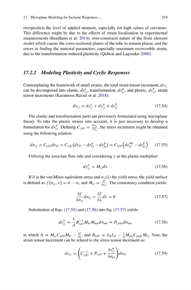
Contemplating the framework of small strains, the total strain tensor increment, dε i j
can be decomposed into elastic, dε
e
i j , transformation, dε
tr
i j , and plastic, dε
p
i j , strain
tensor increments (Karamooz-Ravari et al. 2018):
dε i j = dε
e
i j + dε
tr
i j + dε
p
i j
(17.54)
The elastic and transformation parts are previously formulated using microplane
theory. To take the plastic strains into account, it is just necessary to develop a
formulation for dε
p
i j . Defining C i jkl =
∂σ i j
∂ε
e
i j
, the stress increment might be obtained
using the following relation:
dσ i j = C i jkl dε kl = C i jkl
dε kl − dε
tr
kl − dε
p
kl
= C i jkl
dε
inp
kl − dε
p
kl
(17.55)
Utilizing the associate flow rule and considering λ as the plastic multiplier:
dε
p
i j = M i j dλ
(17.56)
If ¯
σ is the von Mises equivalent stress and σ y (λ) the yield stress, the yield surface
is defined as f
σ i j , λ
= ¯
σ − σ y and M i j =
∂ f
∂σ i j
. The consistency condition yields:
∂ f
∂σ i j
dσ i j +
∂ f
∂λ
dλ = 0
(17.57)
Substitution of Eqs. (17.55) and (17.56) into Eq. (17.57) yields:
dε
p
i j =
1
A
B
−1
i jkl M kl M mn dσ mn = P i jmn dσ mn
(17.58)
in which A = M i j C i jkl M kl −
∂ f
∂λ
, and B i jkl = δ ik δ jl −
1
A
M pq C pqkl M i j . Now, the
strain tensor increment can be related to the stress tensor increment as:
dε i j =
C
−1
i jkl + P i jkl +
∂ε
tr
i j
∂σ kl
dσ kl
(17.59)
319
overpredicts the level of applied moment, especially for high values of curvature.
This difference might be due to the effects of strain localization in experimental
measurements (Reedlunn et al. 2014), over-constraint nature of the finite element
model which causes the cross-sectional planes of the tube to remain planar, and the
errors in finding the material parameters, especially maximum recoverable strain,
due to the transformation-induced plasticity (Qidwai and Lagoudas 2000).
17.2.2 Modeling Plasticity and Cyclic Responses
Contemplating the framework of small strains, the total strain tensor increment, dε i j
can be decomposed into elastic, dε
e
i j , transformation, dε
tr
i j , and plastic, dε
p
i j , strain
tensor increments (Karamooz-Ravari et al. 2018):
dε i j = dε
e
i j + dε
tr
i j + dε
p
i j
(17.54)
The elastic and transformation parts are previously formulated using microplane
theory. To take the plastic strains into account, it is just necessary to develop a
formulation for dε
p
i j . Defining C i jkl =
∂σ i j
∂ε
e
i j
, the stress increment might be obtained
using the following relation:
dσ i j = C i jkl dε kl = C i jkl
dε kl − dε
tr
kl − dε
p
kl
= C i jkl
dε
inp
kl − dε
p
kl
(17.55)
Utilizing the associate flow rule and considering λ as the plastic multiplier:
dε
p
i j = M i j dλ
(17.56)
If ¯
σ is the von Mises equivalent stress and σ y (λ) the yield stress, the yield surface
is defined as f
σ i j , λ
= ¯
σ − σ y and M i j =
∂ f
∂σ i j
. The consistency condition yields:
∂ f
∂σ i j
dσ i j +
∂ f
∂λ
dλ = 0
(17.57)
Substitution of Eqs. (17.55) and (17.56) into Eq. (17.57) yields:
dε
p
i j =
1
A
B
−1
i jkl M kl M mn dσ mn = P i jmn dσ mn
(17.58)
in which A = M i j C i jkl M kl −
∂ f
∂λ
, and B i jkl = δ ik δ jl −
1
A
M pq C pqkl M i j . Now, the
strain tensor increment can be related to the stress tensor increment as:
dε i j =
C
−1
i jkl + P i jkl +
∂ε
tr
i j
∂σ kl
dσ kl
(17.59)