

314
M. R. Karamooz-Ravari et al.
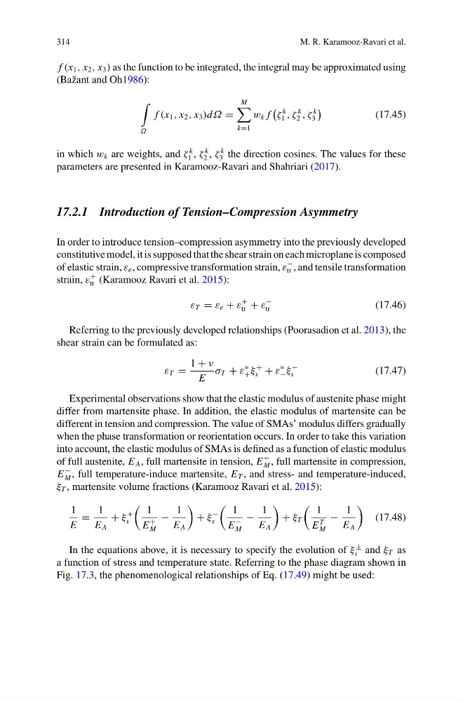
f (x 1 , x 2 , x 3 ) as the function to be integrated, the integral may be approximated using
(Bažant and Oh1986):
Ω
f (x 1 , x 2 , x 3 )dΩ =
M
k=1
w k f
ζ
k
1 , ζ
k
2 , ζ
k
3
(17.45)
in which w k are weights, and ζ
k
1 , ζ
k
2 , ζ
k
3 the direction cosines. The values for these
parameters are presented in Karamooz-Ravari and Shahriari (2017).
17.2.1 Introduction of Tension–Compression Asymmetry
In order to introduce tension–compression asymmetry into the previously developed
constitutive model, it is supposed that the shear strain on each microplane is composed
of elastic strain, ε e , compressive transformation strain, ε
−
tr , and tensile transformation
strain, ε
+
tr (Karamooz Ravari et al. 2015):
ε T = ε e + ε
+
tr + ε
−
tr
(17.46)
Referring to the previously developed relationships (Poorasadion et al. 2013), the
shear strain can be formulated as:
ε T =
1 + ν
E
σ T + ε
∗
+ ξ
+
s + ε
∗
− ξ
−
s
(17.47)
Experimental observations show that the elastic modulus of austenite phase might
differ from martensite phase. In addition, the elastic modulus of martensite can be
different in tension and compression. The value of SMAs’ modulus differs gradually
when the phase transformation or reorientation occurs. In order to take this variation
into account, the elastic modulus of SMAs is defined as a function of elastic modulus
of full austenite, E A , full martensite in tension, E
+
M , full martensite in compression,
E
−
M , full temperature-induce martensite, E T , and stress- and temperature-induced,
ξ T , martensite volume fractions (Karamooz Ravari et al. 2015):
1
E
=
1
E A
+ ξ
+
s
1
E
+
M
−
1
E A
+ ξ
−
s
1
E
−
M
−
1
E A
+ ξ T
1
E
T
M
−
1
E A
(17.48)
In the equations above, it is necessary to specify the evolution of ξ
±
s and ξ T as
a function of stress and temperature state. Referring to the phase diagram shown in
Fig. 17.3, the phenomenological relationships of Eq. (17.49) might be used:
M. R. Karamooz-Ravari et al.
f (x 1 , x 2 , x 3 ) as the function to be integrated, the integral may be approximated using
(Bažant and Oh1986):
Ω
f (x 1 , x 2 , x 3 )dΩ =
M
k=1
w k f
ζ
k
1 , ζ
k
2 , ζ
k
3
(17.45)
in which w k are weights, and ζ
k
1 , ζ
k
2 , ζ
k
3 the direction cosines. The values for these
parameters are presented in Karamooz-Ravari and Shahriari (2017).
17.2.1 Introduction of Tension–Compression Asymmetry
In order to introduce tension–compression asymmetry into the previously developed
constitutive model, it is supposed that the shear strain on each microplane is composed
of elastic strain, ε e , compressive transformation strain, ε
−
tr , and tensile transformation
strain, ε
+
tr (Karamooz Ravari et al. 2015):
ε T = ε e + ε
+
tr + ε
−
tr
(17.46)
Referring to the previously developed relationships (Poorasadion et al. 2013), the
shear strain can be formulated as:
ε T =
1 + ν
E
σ T + ε
∗
+ ξ
+
s + ε
∗
− ξ
−
s
(17.47)
Experimental observations show that the elastic modulus of austenite phase might
differ from martensite phase. In addition, the elastic modulus of martensite can be
different in tension and compression. The value of SMAs’ modulus differs gradually
when the phase transformation or reorientation occurs. In order to take this variation
into account, the elastic modulus of SMAs is defined as a function of elastic modulus
of full austenite, E A , full martensite in tension, E
+
M , full martensite in compression,
E
−
M , full temperature-induce martensite, E T , and stress- and temperature-induced,
ξ T , martensite volume fractions (Karamooz Ravari et al. 2015):
1
E
=
1
E A
+ ξ
+
s
1
E
+
M
−
1
E A
+ ξ
−
s
1
E
−
M
−
1
E A
+ ξ T
1
E
T
M
−
1
E A
(17.48)
In the equations above, it is necessary to specify the evolution of ξ
±
s and ξ T as
a function of stress and temperature state. Referring to the phase diagram shown in
Fig. 17.3, the phenomenological relationships of Eq. (17.49) might be used: