

262
P. Franciosi and M. Spagnuolo
around a common direction of the constitutive fibers. Multi-directional (mD) bundles
can then also be obtained in averaging several 1D bundles. Depending on the chosen
method to reach a same structure objective, the account for the interactions between
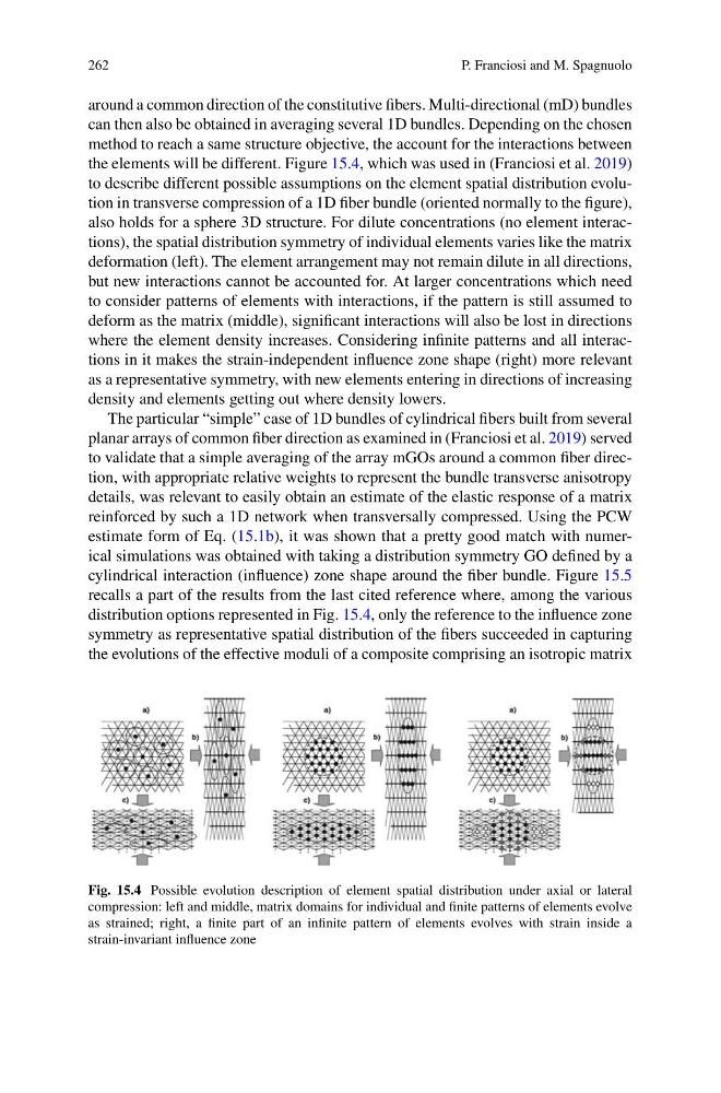
the elements will be different. Figure 15.4, which was used in (Franciosi et al. 2019)
to describe different possible assumptions on the element spatial distribution evolution in transverse compression of a 1D fiber bundle (oriented normally to the figure),
also holds for a sphere 3D structure. For dilute concentrations (no element interactions), the spatial distribution symmetry of individual elements varies like the matrix
deformation (left). The element arrangement may not remain dilute in all directions,
but new interactions cannot be accounted for. At larger concentrations which need
to consider patterns of elements with interactions, if the pattern is still assumed to
deform as the matrix (middle), significant interactions will also be lost in directions
where the element density increases. Considering infinite patterns and all interactions in it makes the strain-independent influence zone shape (right) more relevant
as a representative symmetry, with new elements entering in directions of increasing
density and elements getting out where density lowers.
The particular “simple” case of 1D bundles of cylindrical fibers built from several
planar arrays of common fiber direction as examined in (Franciosi et al. 2019) served
to validate that a simple averaging of the array mGOs around a common fiber direction, with appropriate relative weights to represent the bundle transverse anisotropy
details, was relevant to easily obtain an estimate of the elastic response of a matrix
reinforced by such a 1D network when transversally compressed. Using the PCW
estimate form of Eq. (15.1b), it was shown that a pretty good match with numerical simulations was obtained with taking a distribution symmetry GO defined by a
cylindrical interaction (influence) zone shape around the fiber bundle. Figure 15.5
recalls a part of the results from the last cited reference where, among the various
distribution options represented in Fig. 15.4, only the reference to the influence zone
symmetry as representative spatial distribution of the fibers succeeded in capturing
the evolutions of the effective moduli of a composite comprising an isotropic matrix
Fig. 15.4 Possible evolution description of element spatial distribution under axial or lateral
compression: left and middle, matrix domains for individual and finite patterns of elements evolve
as strained; right, a finite part of an infinite pattern of elements evolves with strain inside a
strain-invariant influence zone
P. Franciosi and M. Spagnuolo
around a common direction of the constitutive fibers. Multi-directional (mD) bundles
can then also be obtained in averaging several 1D bundles. Depending on the chosen
method to reach a same structure objective, the account for the interactions between
the elements will be different. Figure 15.4, which was used in (Franciosi et al. 2019)
to describe different possible assumptions on the element spatial distribution evolution in transverse compression of a 1D fiber bundle (oriented normally to the figure),
also holds for a sphere 3D structure. For dilute concentrations (no element interactions), the spatial distribution symmetry of individual elements varies like the matrix
deformation (left). The element arrangement may not remain dilute in all directions,
but new interactions cannot be accounted for. At larger concentrations which need
to consider patterns of elements with interactions, if the pattern is still assumed to
deform as the matrix (middle), significant interactions will also be lost in directions
where the element density increases. Considering infinite patterns and all interactions in it makes the strain-independent influence zone shape (right) more relevant
as a representative symmetry, with new elements entering in directions of increasing
density and elements getting out where density lowers.
The particular “simple” case of 1D bundles of cylindrical fibers built from several
planar arrays of common fiber direction as examined in (Franciosi et al. 2019) served
to validate that a simple averaging of the array mGOs around a common fiber direction, with appropriate relative weights to represent the bundle transverse anisotropy
details, was relevant to easily obtain an estimate of the elastic response of a matrix
reinforced by such a 1D network when transversally compressed. Using the PCW
estimate form of Eq. (15.1b), it was shown that a pretty good match with numerical simulations was obtained with taking a distribution symmetry GO defined by a
cylindrical interaction (influence) zone shape around the fiber bundle. Figure 15.5
recalls a part of the results from the last cited reference where, among the various
distribution options represented in Fig. 15.4, only the reference to the influence zone
symmetry as representative spatial distribution of the fibers succeeded in capturing
the evolutions of the effective moduli of a composite comprising an isotropic matrix
Fig. 15.4 Possible evolution description of element spatial distribution under axial or lateral
compression: left and middle, matrix domains for individual and finite patterns of elements evolve
as strained; right, a finite part of an infinite pattern of elements evolves with strain inside a
strain-invariant influence zone