

192
A. V. Basalin et al.
models (Alibert et al. 2003; Sciarra et al. 2007; dell’Isola et al. 2012; Auffray et al.
2013; dell’Isola et al. 2015; Rahali et al. 2015; dell’Isola et al. 2016a, b, c). Tensile
experiments (among the others) are widely used for validation of theoretical (and
numerical) predictions (dell’Isola et al. 2016a, b, c; dell’Isola 2017; Giorgio 2016,
Turco et al. 2016; Placidi et al. 2017).
However, tensile tests have a number of features, which have to be taken into
account while planning an experiment and interpreting its results. A specially shaped
specimen is usually used. Specimen should have a gauge area and areas for their fixing
in experimental setup. Areas for fixing might affect stress and strain fields in gauge
area. These effects can be minimized by increasing the length of gauge area. This
method is employed for static experiments. In case of dynamic loading, there are
some length limitations for gauge area due to the wave effects. Therefore, influence
of fixing areas can be significant. Moreover, strain localization and necking process
cause difficulties in obtaining true strength and strain characteristics of material.
This paper considers some distinguishing features of high strain rate tension
experiments within the strain rate range from 500 to 5000 1/s.
13.2 Split Hopkinson bar Technique
One of the most widely used loading techniques at high strain rates is the split
Hopkinson pressure bar (SHPB) or the Kolsky method developed by Kolsky (1949).
There are some review works (Field et al. 1994; Bacon and Lataillade 2001; Gama
et al. 2004) that describe a historical background of SHPB method. This method can
be easily implemented and well justified and realized theoretically.
Davies (1948) and Kolsky (1949) proposed to use SHPB for compression tests
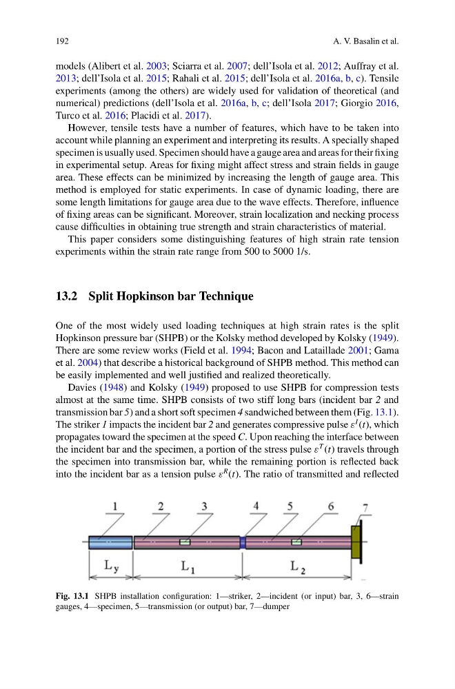
almost at the same time. SHPB consists of two stiff long bars (incident bar 2 and
transmission bar 5) and a short soft specimen 4 sandwiched between them (Fig. 13.1).
The striker 1 impacts the incident bar 2 and generates compressive pulse ε
I (t), which
propagates toward the specimen at the speed C. Upon reaching the interface between
the incident bar and the specimen, a portion of the stress pulse ε
T (t) travels through
the specimen into transmission bar, while the remaining portion is reflected back
into the incident bar as a tension pulse ε
R (t). The ratio of transmitted and reflected
Fig. 13.1 SHPB installation configuration: 1—striker, 2—incident (or input) bar, 3, 6—strain
gauges, 4—specimen, 5—transmission (or output) bar, 7—dumper
A. V. Basalin et al.
models (Alibert et al. 2003; Sciarra et al. 2007; dell’Isola et al. 2012; Auffray et al.
2013; dell’Isola et al. 2015; Rahali et al. 2015; dell’Isola et al. 2016a, b, c). Tensile
experiments (among the others) are widely used for validation of theoretical (and
numerical) predictions (dell’Isola et al. 2016a, b, c; dell’Isola 2017; Giorgio 2016,
Turco et al. 2016; Placidi et al. 2017).
However, tensile tests have a number of features, which have to be taken into
account while planning an experiment and interpreting its results. A specially shaped
specimen is usually used. Specimen should have a gauge area and areas for their fixing
in experimental setup. Areas for fixing might affect stress and strain fields in gauge
area. These effects can be minimized by increasing the length of gauge area. This
method is employed for static experiments. In case of dynamic loading, there are
some length limitations for gauge area due to the wave effects. Therefore, influence
of fixing areas can be significant. Moreover, strain localization and necking process
cause difficulties in obtaining true strength and strain characteristics of material.
This paper considers some distinguishing features of high strain rate tension
experiments within the strain rate range from 500 to 5000 1/s.
13.2 Split Hopkinson bar Technique
One of the most widely used loading techniques at high strain rates is the split
Hopkinson pressure bar (SHPB) or the Kolsky method developed by Kolsky (1949).
There are some review works (Field et al. 1994; Bacon and Lataillade 2001; Gama
et al. 2004) that describe a historical background of SHPB method. This method can
be easily implemented and well justified and realized theoretically.
Davies (1948) and Kolsky (1949) proposed to use SHPB for compression tests
almost at the same time. SHPB consists of two stiff long bars (incident bar 2 and
transmission bar 5) and a short soft specimen 4 sandwiched between them (Fig. 13.1).
The striker 1 impacts the incident bar 2 and generates compressive pulse ε
I (t), which
propagates toward the specimen at the speed C. Upon reaching the interface between
the incident bar and the specimen, a portion of the stress pulse ε
T (t) travels through
the specimen into transmission bar, while the remaining portion is reflected back
into the incident bar as a tension pulse ε
R (t). The ratio of transmitted and reflected
Fig. 13.1 SHPB installation configuration: 1—striker, 2—incident (or input) bar, 3, 6—strain
gauges, 4—specimen, 5—transmission (or output) bar, 7—dumper