

349
and its incident angle. In current practice, antireflective coatings are
designed for optimal performance for specified wavelengths and
angles. Common coatings are usually designed for infrared (IR),
visible, and ultraviolet (UV) spectra, depending on the application.
Broader bands are possible but very expensive. Some less expensive
coatings use so-called absorbing antireflective (AR) materials for
situations in which low reflectivities are needed but high transmissions are not necessary.
The functions of increasing light transmission and contrast using
antireflective materials are often surprising to many, but their
origins go back to seminal explorations of light transmission effects
through coatings. In the 19
th century, tarnishes caused by chemical reactions with the environment developed on optical glasses of
the day were common and exhibited reduced reflections. They
were also generally thought to reduce light transmission. Lord
Rayleigh (John Strutt), well-known for his many contributions to
optics, looked into the problem and experimentally observed that
tarnished pieces often transmitted more rather than less light—a
seemingly surprising result. The general reason underlying this
phenomenon is based on the fact that the total amount of light
impinging on a surface must in sum be reflected, transmitted, or
absorbed (see Section 4.7). If the amount of light reflected from a
surface is reduced, more must be transmitted or absorbed. A more
precise explanation centers around the fact that the index of refraction of the tarnish lies between that of air and of glass, and both the
air-tarnish and the tarnish-glass interfaces exhibit reduced reflections that are less in sum than the original air-glass interface.
Antireflection coatings now commonly consist of multiple layers
of materials with varying refractive indices. Material types and layer
thicknesses are designed to increase the constructive interference
in light transmitted through the layers and destructive interference
in light reflected from the several interfaces. Fundamental effects
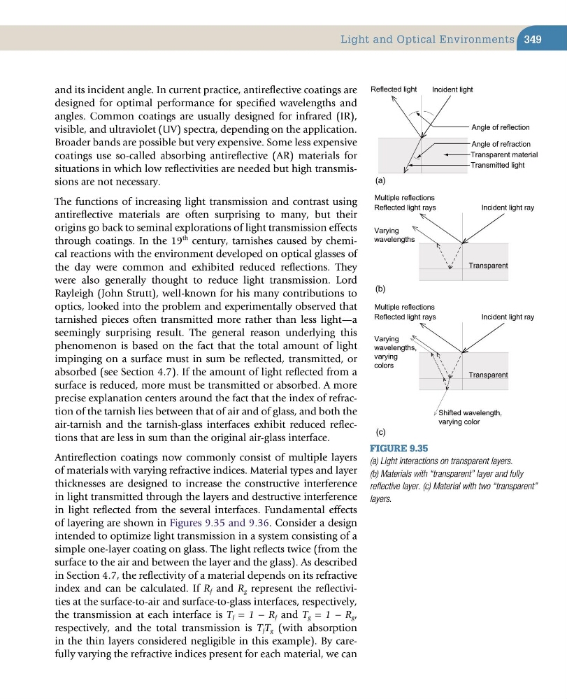
of layering are shown in Figures 9.35 and 9.36. Consider a design
intended to optimize light transmission in a system consisting of a
simple one-layer coating on glass. The light reflects twice (from the
surface to the air and between the layer and the glass). As described
in Section 4.7, the reflectivity of a material depends on its refractive
index and can be calculated. If R f and R g represent the reflectivities at the surface-to-air and surface-to-glass interfaces, respectively,
the transmission at each interface is T f = 1 − R f and T g = 1 − R g ,
respectively, and the total transmission is T f T g (with absorption
in the thin layers considered negligible in this example). By carefully varying the refractive indices present for each material, we can
Figure 9.35
(a) Light interactions on transparent layers.
(b) Materials with “transparent” layer and fully
reflective layer. (c) Material with two “transparent”
layers.
(b)
(a)
Transparent material
Reflected light
Incident light
Angle of refraction
Angle of reflection
Transmitted light
Transparent
Multiple reflections
Incident light ray
Reflected light rays
Varying
wavelengths
(c)
Transparent
Multiple reflections
Incident light ray
Reflected light rays
Varying
wavelengths,
varying
colors
Shifted wavelength,
varying color
Light and Optical Environments
and its incident angle. In current practice, antireflective coatings are
designed for optimal performance for specified wavelengths and
angles. Common coatings are usually designed for infrared (IR),
visible, and ultraviolet (UV) spectra, depending on the application.
Broader bands are possible but very expensive. Some less expensive
coatings use so-called absorbing antireflective (AR) materials for
situations in which low reflectivities are needed but high transmissions are not necessary.
The functions of increasing light transmission and contrast using
antireflective materials are often surprising to many, but their
origins go back to seminal explorations of light transmission effects
through coatings. In the 19
th century, tarnishes caused by chemical reactions with the environment developed on optical glasses of
the day were common and exhibited reduced reflections. They
were also generally thought to reduce light transmission. Lord
Rayleigh (John Strutt), well-known for his many contributions to
optics, looked into the problem and experimentally observed that
tarnished pieces often transmitted more rather than less light—a
seemingly surprising result. The general reason underlying this
phenomenon is based on the fact that the total amount of light
impinging on a surface must in sum be reflected, transmitted, or
absorbed (see Section 4.7). If the amount of light reflected from a
surface is reduced, more must be transmitted or absorbed. A more
precise explanation centers around the fact that the index of refraction of the tarnish lies between that of air and of glass, and both the
air-tarnish and the tarnish-glass interfaces exhibit reduced reflections that are less in sum than the original air-glass interface.
Antireflection coatings now commonly consist of multiple layers
of materials with varying refractive indices. Material types and layer
thicknesses are designed to increase the constructive interference
in light transmitted through the layers and destructive interference
in light reflected from the several interfaces. Fundamental effects
of layering are shown in Figures 9.35 and 9.36. Consider a design
intended to optimize light transmission in a system consisting of a
simple one-layer coating on glass. The light reflects twice (from the
surface to the air and between the layer and the glass). As described
in Section 4.7, the reflectivity of a material depends on its refractive
index and can be calculated. If R f and R g represent the reflectivities at the surface-to-air and surface-to-glass interfaces, respectively,
the transmission at each interface is T f = 1 − R f and T g = 1 − R g ,
respectively, and the total transmission is T f T g (with absorption
in the thin layers considered negligible in this example). By carefully varying the refractive indices present for each material, we can
Figure 9.35
(a) Light interactions on transparent layers.
(b) Materials with “transparent” layer and fully
reflective layer. (c) Material with two “transparent”
layers.
(b)
(a)
Transparent material
Reflected light
Incident light
Angle of refraction
Angle of reflection
Transmitted light
Transparent
Multiple reflections
Incident light ray
Reflected light rays
Varying
wavelengths
(c)
Transparent
Multiple reflections
Incident light ray
Reflected light rays
Varying
wavelengths,
varying
colors
Shifted wavelength,
varying color
Light and Optical Environments