

287
incident beam and strong intensity, and Raman scattering, which is
inelastic and exhibits a weaker intensity at higher and lower frequencies than the incident beam. Therefore, in Raman spectroscopy, the
vibrational frequency and thus the wavelength of groups of atoms
are measured as a shift from the incident beam frequency.
The laser is an ideal source for Raman scattering because it is
bright, quasimonochromatic, and available in a wide range of frequencies. A Raman spectrum is normally measured in the UVvisible region where the excitation and the Raman lines appear.
It is a complementary technique to IR spectroscopy because some
vibrational modes of materials are IR-active, whereas others are
Raman-active. In the case of nanomaterials, Raman spectroscopy
has been used extensively to characterize carbon nanotubes by
analyzing their mode frequencies as a function of size and chirality. In addition, Raman spectroscopy has been shown to probe
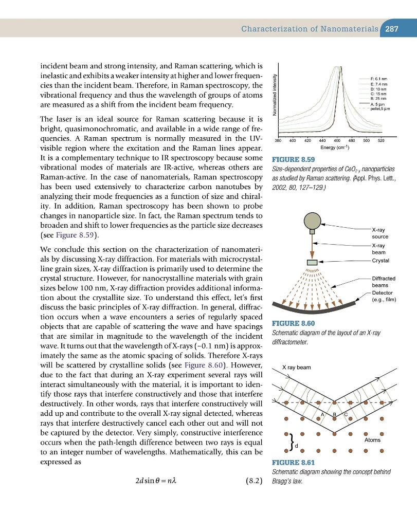
changes in nano particle size. In fact, the Raman spectrum tends to
broaden and shift to lower frequencies as the particle size decreases
(see Figure 8.59).
We conclude this section on the characterization of nanomaterials by discussing X-ray diffraction. For materials with microcrystalline grain sizes, X-ray diffraction is primarily used to determine the
crystal structure. However, for nanocrystalline materials with grain
sizes below 100 nm, X-ray diffraction provides additional information about the crystallite size. To understand this effect, let’s first
discuss the basic principles of X-ray diffraction. In general, diffraction occurs when a wave encounters a series of regularly spaced
objects that are capable of scattering the wave and have spacings
that are similar in magnitude to the wavelength of the incident
wave. It turns out that the wavelength of X-rays (∼0.1 nm) is approximately the same as the atomic spacing of solids. Therefore X-rays
will be scattered by crystalline solids (see Figure 8.60). However,
due to the fact that during an X-ray experiment several rays will
interact simultaneously with the material, it is important to identify those rays that interfere constructively and those that interfere
destructively. In other words, rays that interfere constructively will
add up and contribute to the overall X-ray signal detected, whereas
rays that interfere destructively cancel each other out and will not
be captured by the detector. Very simply, constructive interference
occurs when the path-length difference between two rays is equal
to an integer number of wavelengths. Mathematically, this can be
expressed as
2d
n
sinθ
λ
=
(8.2)
Figure 8.59
Size-dependent properties of CeO 2-y nanoparticles
as studied by Raman scattering. (Appl. Phys. Lett.,
2002, 80, 127–129.)
Normalized intensity
Energy (cm -1 )
380
400
420
440
460
480
500
520
E: 7.4 nm
F: 6.1 nm
D: 10 nm
C: 15 nm
B: 25 nm
A: 5 µm
pellet,5 µm
Figure 8.60
Schematic diagram of the layout of an X-ray
diffractometer.
Diffracted
beams
Detector
(e.g., film)
X-ray
beam
X-ray
source
Crystal
Figure 8.61
Schematic diagram showing the concept behind
Bragg’s law.
} d
A
B
C
Atoms
X ray beam
Characterization of Nanomaterials
incident beam and strong intensity, and Raman scattering, which is
inelastic and exhibits a weaker intensity at higher and lower frequencies than the incident beam. Therefore, in Raman spectroscopy, the
vibrational frequency and thus the wavelength of groups of atoms
are measured as a shift from the incident beam frequency.
The laser is an ideal source for Raman scattering because it is
bright, quasimonochromatic, and available in a wide range of frequencies. A Raman spectrum is normally measured in the UVvisible region where the excitation and the Raman lines appear.
It is a complementary technique to IR spectroscopy because some
vibrational modes of materials are IR-active, whereas others are
Raman-active. In the case of nanomaterials, Raman spectroscopy
has been used extensively to characterize carbon nanotubes by
analyzing their mode frequencies as a function of size and chirality. In addition, Raman spectroscopy has been shown to probe
changes in nano particle size. In fact, the Raman spectrum tends to
broaden and shift to lower frequencies as the particle size decreases
(see Figure 8.59).
We conclude this section on the characterization of nanomaterials by discussing X-ray diffraction. For materials with microcrystalline grain sizes, X-ray diffraction is primarily used to determine the
crystal structure. However, for nanocrystalline materials with grain
sizes below 100 nm, X-ray diffraction provides additional information about the crystallite size. To understand this effect, let’s first
discuss the basic principles of X-ray diffraction. In general, diffraction occurs when a wave encounters a series of regularly spaced
objects that are capable of scattering the wave and have spacings
that are similar in magnitude to the wavelength of the incident
wave. It turns out that the wavelength of X-rays (∼0.1 nm) is approximately the same as the atomic spacing of solids. Therefore X-rays
will be scattered by crystalline solids (see Figure 8.60). However,
due to the fact that during an X-ray experiment several rays will
interact simultaneously with the material, it is important to identify those rays that interfere constructively and those that interfere
destructively. In other words, rays that interfere constructively will
add up and contribute to the overall X-ray signal detected, whereas
rays that interfere destructively cancel each other out and will not
be captured by the detector. Very simply, constructive interference
occurs when the path-length difference between two rays is equal
to an integer number of wavelengths. Mathematically, this can be
expressed as
2d
n
sinθ
λ
=
(8.2)
Figure 8.59
Size-dependent properties of CeO 2-y nanoparticles
as studied by Raman scattering. (Appl. Phys. Lett.,
2002, 80, 127–129.)
Normalized intensity
Energy (cm -1 )
380
400
420
440
460
480
500
520
E: 7.4 nm
F: 6.1 nm
D: 10 nm
C: 15 nm
B: 25 nm
A: 5 µm
pellet,5 µm
Figure 8.60
Schematic diagram of the layout of an X-ray
diffractometer.
Diffracted
beams
Detector
(e.g., film)
X-ray
beam
X-ray
source
Crystal
Figure 8.61
Schematic diagram showing the concept behind
Bragg’s law.
} d
A
B
C
Atoms
X ray beam
Characterization of Nanomaterials